- Home
- Users & Science
- Scientific Documentation
- ESRF Highlights
- ESRF Highlights 2001
- The X-ray Source
- In-vacuum Undulators
In-vacuum Undulators
In 2001, a significant effort went towards the construction of four 2 metre-long in-vacuum undulators (Table 8, Figure 179). Their operation at a much smaller magnetic gap than conventional undulators, in which the magnets are located in the air outside of the vacuum chamber, permits in-vacuum undulators to produce higher photon fluxes and brilliance. This is particularly important at energies above 30 keV. They are short period devices based on nickel coated permanent magnet blocks of type Sm2Co17. Compared to NdFeB, Sm2Co17 offers a good compromise between high peak field and temperature resistance (vacuum baking at 150°C) and radiation damage.
 |
Table 8: The new in-vacuum undulators. |
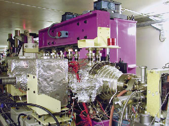 |
Fig. 179: In-vacuum undulator installed in the tunnel of the storage ring. |
The usual magnetic field correction methods used for conventional undulators are applicable to in vacuum undulators (Figure 180).
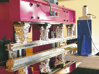 |
Fig. 180: Field measurement of an in-vacuum undulator. |
In particular, spectrum shimming has a significant impact on the potential use of high harmonics of undulator spectra in the energy range of 50 to 100 keV. Figure 181 shows the computed photon fluxes versus energy in a finite square aperture (1mm x 1mm) at 30 m from the source (U23 with a gap of 6 mm). The red curve is the spectrum computed with the actual magnetic field (including residual errors) and the blue curve corresponds to the output from an ideal (error free). In both cases the calculations assume standard ESRF electron beam (I = 200 mA), emittance 4 nm (40 pm) horizontally (vertically) and a device installed in a high beta straight such as ID22.The differences between both spectral fluxes are essentially visible on the high harmonics. In particular the losses observed on the harmonic 15 (E = 95 keV) are lower than 30%.
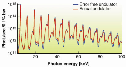 |
Fig. 181: Spectral fluxes computed from measured magnetic field (red) and an error free undulator (blue). |
The construction of in-vacuum undulators will be pursued in 2002.
partners


European Synchrotron Radiation Facility - 71, avenue des Martyrs, CS 40220, 38043 Grenoble Cedex 9, France.