- Home
- Users & Science
- Scientific Documentation
- ESRF Highlights
- ESRF Highlights 2015
- Enabling technologies
- Sub-30 nm focusing with figured multilayer Kirkpatrick-Baez mirrors
Sub-30 nm focusing with figured multilayer Kirkpatrick-Baez mirrors
The upgraded ID16A nano-imaging end station was recently equipped with two new Kirkpatrick-Baez focusing systems based on figured mirrors and in-house coated graded multilayers. They consist of W/B4C with d-spacings down to 2 nm and possess steep longitudinal thickness gradients to comply with Bragg’s law along the full beam footprint. They operate at 17 keV and 33.6 keV, respectively. Users now have access to beam sizes down to 27 x 21 nm2 (H x V) with a photon flux up to 10exp12 ph/s.
The Kirkpatrick-Baez (KB) configuration is commonly used to produce a focused X-ray beam. In this scheme, one mirror focuses the beam vertically and a second mirror horizontally. Contrary to previous setups [1], the new systems on ID16A use mirrors that were polished to their elliptical cylinder figures, thus obtaining lower figure errors with higher curvature than achievable with dynamically bent mirrors.
Often KB systems are used in combination with multilayer coatings. This allows the mirrors to be used at larger incidence angles and is therefore beneficial to increase the acceptance for a given mirror length. Multilayers reflect an energy band pass of 1-5% at an angle given by Bragg’s law. Consequently, due to the strong variation in the local incidence angle on the mirror, the multilayer d-spacing must be graded to reflect along the full beam footprint on each mirror.
The new ID16A beamline is 185 m long and operates at fixed photon energies that are selected by a horizontally focusing multilayer. The multilayer generates a 50 μm wide secondary source in the horizontal direction at 40 m from the undulator. Since the source shape is strongly elliptical, this layout is required to obtain an approximately circular focal spot at the sample. Consequently, the source distances with respect to the KB are 183.5 m in the vertical and 144.6 m in the horizontal direction. By choosing the respective image distances to 0.1 m and 0.043 m, a circular focal spot can indeed be generated.
Two independent nano-focusing KB setups are installed in the experimental hutch to operate the end station either at 17 keV or at 33.6 keV. The total mirror lengths are only 70 mm (vertical) and 36 mm (horizontal). The respective mirror pairs differ in curvature and grazing angle but they were designed in such a way as to provide the same focal spot size at both photon energies. Assuming perfect optics, one would expect a diffraction limited spot size of 7-8 nm FWHM, as confirmed by wave optical simulations [2]. Including the measured figure errors of the mirrors, the expected spot size may increase slightly. The source size contribution should also blur the focal spot to at least 15 nm FWHM.
 |
|
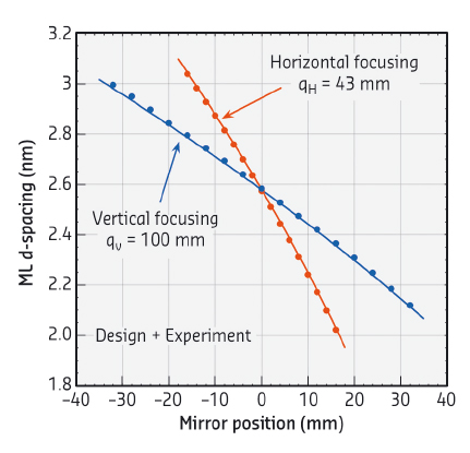
Fig. 145: D-spacing profiles of the horizontally focusing (red) and the vertically focusing (blue) multilayers (ML). Solid lines indicate theoretical curves, dots show experimental data. |
The multilayer coatings consist of W/B4C with d-spacings down to 2 nm. The multilayers were deposited at the ESRF Multilayer Laboratory in dynamic mode where the substrates are moved in front of each cathode. Steep longitudinal gradients were achieved by varying the speed during each duty cycle. Based on X-ray reflectivity measurements at 8048 eV, the estimated total KB efficiency is about 45% at 17 keV and 75% at 33.6 keV, and the total bandwidth is 1.5% FWHM in both cases. Figure 145 shows theoretical and experimental d-spacing profiles for both the horizontally and the vertically focusing multilayer of the 17 keV KB system. The total offset errors are close to 0.3% and the variations are below 0.5%. Taking into account both the involved energy bandwidths and the gradient accuracy, the full source intensity can be transmitted by the optical system to the experiment.
 |
|
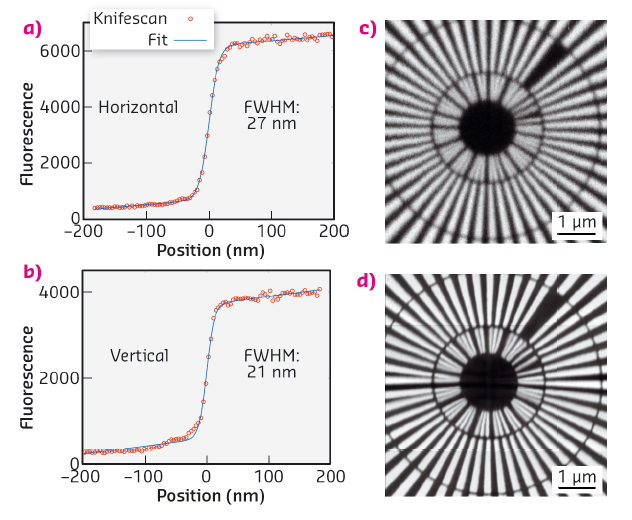
Fig. 146: Left: Knife edge scans at 33.6 keV through the focal spot in fluorescence mode: (a) horizontal scan; (b) vertical scan. The blue lines are error functions fitted to the experimental data. Right: X-ray fluorescence imaging at 17 keV: (c) previous setup at ID22NI using a dynamically bent KB; (d) new setup at ID16A using a figured KB. |
Both KB systems were installed and commissioned at ID16A. The size of the focal spot was measured using knife edge scans along both the horizontal and the vertical directions. The resulting FWHM spot size is 23 nm (hor) x 37 nm (ver) at 17 keV and 27 nm (hor) x 21 nm (ver) at 33.6 keV (Figure 146, left). The respective photon fluxes are 7x10¹¹ ph/s and 6x10¹⁰ ph/s. Discrepancies between the measured and expected spot sizes have not yet been explained but may be due to the physical extent of the knife edge or artefacts from the opto-mechanical assembly.
Fluorescence imaging was carried out to study image quality and resolution and to compare them with data from the previous KB system used on ID22NI. The pictures in Figure 146 (right) show Siemens star images taken at ID22NI (c) and ID16A (d) and clearly demonstrate the improved spatial resolution with the new system.
Principal publication and authors
C. Morawe, R. Barrett, P. Cloetens, B. Lantelme, J.-C. Peffen and A. Vivo, Proc. SPIE 9588, 958803 (2015); doi: 10.1117/12.2189279, with additional contributions from A. Pacureanu, Y. Yang, J.C. da Silva and R. Baker.
ESRF
References
[1] R. Barrett et al., Proc. SPIE 8139, 813904 (2011); doi: 10.1117/12.894735.
[2] M. Osterhoff, C. Morawe, Proc. SPIE 8502, 850208 (2012); doi: 10.1117.12.928938.
partners


European Synchrotron Radiation Facility - 71, avenue des Martyrs, CS 40220, 38043 Grenoble Cedex 9, France.