- Home
- Users & Science
- Scientific Documentation
- ESRF Highlights
- ESRF Highlights 2012
- Enabling technologies
- Application of wave optical simulations to focusing X-ray multilayers
Application of wave optical simulations to focusing X-ray multilayers
Many experimental stations at modern synchrotron or FEL sources use X-ray focusing devices that produce spots below 100 nm using a variety of optical elements. A very popular optical scheme is the Kirkpatrick-Baez (KB) setup [1] where two perpendicularly oriented curved mirrors focus the beam independently in the vertical and the horizontal direction, respectively. To increase their numerical aperture, that is, to obtain smaller focal spots, the traditional total reflection mirrors can be replaced by graded multilayers, allowing for steeper grazing angles. While wave optical models for curved total reflection mirrors have been developed in the past, an equivalent description for curved graded multilayers was missing.
Recently, a new software tool was developed at the ESRF that can perform wave optical simulations on curved multilayer optics [2]. It is based on a Takagi-Taupin approach in the two-beam approximation. Outside the multilayer structure the beam is propagated by phase ray tracing and by solving the Kirchhoff integral. Extended sources can be modelled by superposition of point sources. The spatial coherence can be varied by the degree of random averaging of amplitude and phase of the point sources and by their distribution in space.
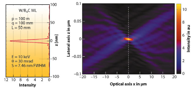
The wave-optical simulations show that diffraction limited focal spots of less than 8 nm full width at half maximum (FWHM) can be expected using realistic curved multilayer structures with d-spacings of the order of 2 nm and reflectivities of more than 70%. This is in good agreement with the best available experimental data [3]. Figure 140 shows the simulated intensity distribution near the image plane at q = 100 mm from a 50 mm long curved W/B4C multilayer positioned at p = 100 m from a point source. The resulting spot size of 7.5 nm FWHM agrees with the diffraction limit estimated from a straight aperture (thin lens approach).
 |
|
Fig. 140: Simulated intensity distribution near the focal spot at q = 100 mm from a 50 mm long curved W/B4C multilayer positioned at p = 100 m from a point source. Further parameters are indicated in the vertical cross section reported on the left. |
The surface figure error of the underlying mirror substrates is a performance limiting factor that can be taken into account by the simulation programme. Applying frequently measured height error spectra with spatial frequencies in the millimetre range indicates an intensity transfer from the main peak into the side lobes while its width remains constant.
The simulation of finite and incoherent storage ring X-ray sources returns focal spots that are blurred from their original diffraction limited size to the de-magnified image of the source, as expected from geometrical optics.
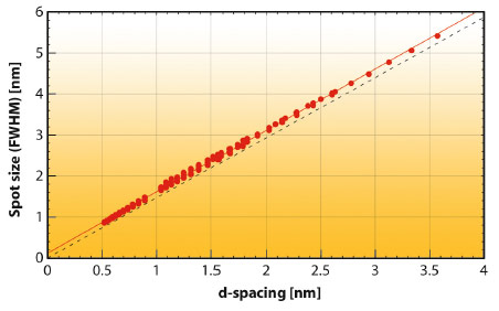
In order to explore fundamental multilayer focusing limits, a large number of different curved multilayers with d-spacings as low as 0.5 nm were simulated, approaching the ultimate limit of layered structures made of alternating materials (two atomic layers). Figure 141 shows that all data points follow a linear slope converging only 0.1 nm above the expected zero crossing. There is no evidence of a major deviation from the diffraction limit down to spot sizes below 1 nm.
 |
|
Fig. 141: Simulated focal spot size (circles) as a function of the multilayer d-spacing at various energies from 12.4 keV to 49.6 keV and for 50 to 300 bi-layers. The solid line is a linear fit to all data points. The broken line corresponds to the diffraction limit of a straight aperture. |
The simulations confirm that the modified Bragg equation, corrected for refraction in the stack, but derived for flat multilayers is a very good approximation for the design of curved multilayer mirrors. They also suggest that curved multilayers can be considered as achromatic optical elements with respect to the focal spot size and that their local reflectivity spectra can be approximated using Parratt’s formalism [4] for flat multilayers.
These results are of fundamental importance for the fabrication of curved graded multilayers for third-generation synchrotron beamlines since they validate the present design approach [5] on a wave-optical level.
Principal publication and authors
M. Osterhoff (a,b) and Ch. Morawe (b), Proc. SPIE 8502, 850208 (2012); doi: 10.1117.12.928938
(a) Georg-August University, Göttingen (Germany)
(b) ESRF
References
[1] P. Kirkpatrick and A.V. Baez, Journal of the Optical Society of America 38, 766 (1948).
[2] M. Osterhoff, Ch. Morawe, C. Ferrero and J-P. Guigay, Optics Letters 37, 3705 (2012).
[3] H. Mimura et al., Nature Physics 6, 122 - 125 (2010).
[4] L.G. Parratt, Phys. Rev. 45, 359 (1954).
[5] Ch. Morawe and M. Osterhoff, X-Ray Optics and Instrumentation, 479631 (2010).
partners


European Synchrotron Radiation Facility - 71, avenue des Martyrs, CS 40220, 38043 Grenoble Cedex 9, France.