Lattice studies
The lattice of the ESRF storage ring was designed with 32 long straight sections of alternating high and low horizontal beta values. This currently provides 5 m of available space for insertion devices. The ESRF Upgrade Programme proposes to increase the length of selected insertion device straight sections from 5 to 7 m. This will provide a higher level of brilliance and increased insertion device (ID) flexibility. For example, longer insertion devices for a single beamline, sharing of the straight sections between two experimental stations using the canted undulator approach, reshuffling RF cavities layout and freeing straight section space for new beamlines are possible uses of the gained ID length.
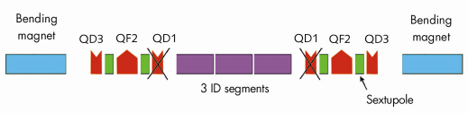
The first step of this programme was achieved in 2006 with the implementation in USM of a new lattice in which the 2 quadrupoles (QD1 and QD8) located on both sides of the undulators were no longer powered (Figure 141). These quadrupoles can be removed and longer (6 m) insertion devices installed.
 |
|
Fig. 141: Schematic lattice design of a long high beta straight section. Bending magnets, quadrupole and sextupoles are shown in blue, red and green respectively. The segments of the insertion devices are represented in purple. With the new lattice in use, the quadrupole family QD1 on both sides of the insertion devices is no longer powered and can be removed extending the total length of straight section available to insertion devices from 5 to 6 m. On the low beta straight sections, the quadrupole families QD1,QF2 and QD3 becomes QD8,QF7 and QD6. The last quadrupole QD8 adjacent to a low beta undulator have been switched off in the new lattice settings. |
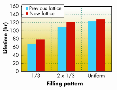
This new type of lattice with no current in QD1 and QD8 has been in use during USM since October 2006. The lifetime of the stored electron beam was lower than that achieved previously resulting in higher beam losses in the ring tunnel. Further lattice investigations were carried out in 2007. An improved lifetime was achieved by increasing the vertical tune by one integer, which necessitated the retuning of all quadrupole and sextupole currents. The electron beam sizes and divergences of the modified lattice present negligible change in the horizontal plane. The greatest change is in the vertical plane and corresponds to a 3 m vertical beta in the middle of the insertion device straight section as opposed to 3.5 m for the lattice that has been in use since October 2006. Measurements show that the lifetime of the beam in this new lattice is slightly longer than that achievedpreviously with the lattice where all quadrupoles were powered (in use between 1996 and 2006). This is illustrated in Figure 142.
 |
|
Fig. 142: Lifetime achieved with a ring current of 100 mA in 1/3, 2 x 1/3 and uniform filling mode with the previous lattice settings with all quadrupoles powered (in blue) and the new lattice (in red). |
 |
|
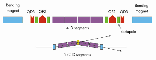
Fig. 143: Modified 7m long straight section with 4 insertion device segments or alternatively two longer undulator segments that are canted in order to generate two X-ray beams to independent beamports. |
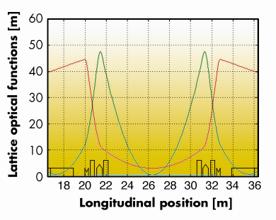
A further increase of the length of insertion devices from 6 to 7 m is possible by redesigning the QF2 and QF7 quadrupole for a shorter length and by displacing the sextupoles adjacent to the undulator. This will require the manufacture of new quadruples with a field gradient of around 25 T/m. A schematic of such a 7 m straight section is shown in Figure 143. The horizontal and vertical beta functions in a low beta straight section are presented in Figure 144.
 |
|
Fig. 144: Beta-functions in a 7 m long low beta straight section. |
In order to minimise costs and shutdown time, the 7 m long straight sections will not be implemented on all straight sections in one go, rather one by one on a limited number of sectors. The drawback of such a strategy is that the symmetry of the lattice will be broken and consequently this may have a detrimental effect on the dynamic aperture resulting in a reduction of the injection efficiency and lifetime. Extensive calculations and experiments are being carried out to simulate the symmetry break produced by such 7 m straight sections. Obviously, the behaviour of a 7 m long straight section cannot be tested experimentally in advance since magnets and vacuum chambers need to be manufactured and installed at the right location. However, on the existing lattice, it is possible to detune a single straight section and break the periodicity by individually powering the magnets of the straight section. Such detuned straight sections generate a modification of the beta function and the displaced magnets excite resonances in the lattice in a manner similar to those observed on a 7 m straight section. The experimental investigations of the lattice with one or several detuned straight sections constitutes therefore a very useful study.
Detuning requires the powering of the quadrupole and sextupole in the associated straight section independently of those of the same quadrupoles in the other straight sections. This capability was implemented several years ago on three high beta straight sections (ID04, ID06 and ID20) and one low beta straight section (ID11). Various combinations of detuning have been implemented during lattice tests with 1, 2 or 3 sections detuned. In each case, similar lifetime and on-momentum horizontal aperture could be observed once the current settings of the quadrupole and sextupole within the detuned straight section had been re-optimised.
partners


European Synchrotron Radiation Facility - 71, avenue des Martyrs, CS 40220, 38043 Grenoble Cedex 9, France.