- Home
- Users & Science
- Scientific Documentation
- ESRF Highlights
- ESRF Highlights 2004
- Surface and Interface Science
- Surface X-ray Diffraction of an Ultra-thin Al2O3 Layer on NiAl(110)
Surface X-ray Diffraction of an Ultra-thin Al2O3 Layer on NiAl(110)
Aluminium oxide, a seemingly unimportant powder, plays a key role as an ultra-thin ceramic film in a variety of high-tech applications, such as high temperature corrosion protection in space, highly active catalytic materials and new types of permanent memory chips. The structure of ultra-thin, ordered Al2O3 layers has puzzled surface scientists for more than a decade [1]. Ultra-thin, well-ordered Al2O3 layers can be prepared by controlled oxidation of NiAl(110) single crystals. As the main result of this study it was found that the thinnest, stable aluminium oxide layer consists of only two oxygen and two aluminium ion layers, which are strongly distorted by the interaction with the NiAl substrate.
To unravel the structure of the Al2O3 layer, a surface X-ray diffraction experiment was performed at the ESRF surface science beamline ID32 and at BW2 at HASYLAB. The oxide layer was prepared in the home lab in Stuttgart and was then shipped to the ESRF in a surface X-ray diffraction baby chamber under UHV conditions. Figure 94a shows one half of the in-plane diffraction pattern obtained at a photon energy of 10.5 keV (the second half can be obtained by rotation of 180°). The huge in-plane unit cell of the oxide layer (a = 10.59 Å, b = 18.01 Å as compared to the NiAl substrate a = 4.083 Å, b = 2.887 Å) gives rise to a large number of reflections, which can be mapped out by surface X-ray diffraction. From such an in-plane diffraction pattern model, independent real space information may be obtained directly by the calculation of the so-called Patterson map, presented in Figure 94b. The Patterson map yields direct information about the sum and difference vectors of different atoms in the surface plane. Close to the border of the unit cell (indicated by the black line), a pattern with locally hexagonal symmetry prevails, which is an indication that hexagons with 0.3 nm side length are an element of the structure. A hexagon with 0.3 nm side length would give rise to the diffraction spots in Figure 94a, which are connected by the red lines.
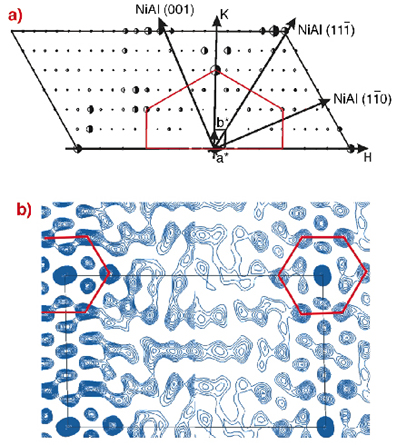 |
Fig. 94: a) One half of the measured structure factors (full half circles) together with the best fit structure factors (open half circles). The oxide layer H and K directions are indicated together with the NiAl substrate coordinates. The oxide layer is only commensurate along the NiAl(1-10) direction. b) Comparison between experimental (left part) and theoretical (right part) Patterson maps. |
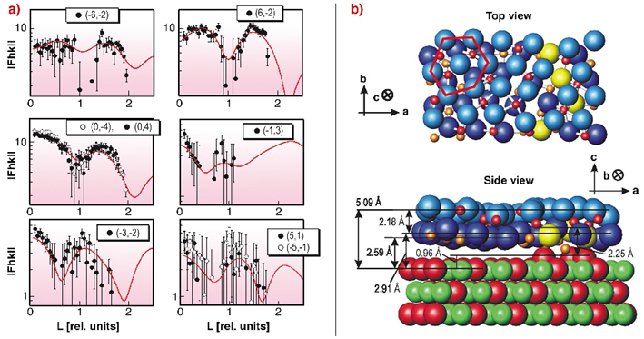
To get information about the full 3D structure of the layer, surface rods with momentum transfer perpendicular to the surface were examined. In Figure 95a the surface rods for different in-plane momentum transfers are plotted together with the best fit result. The surface rods show a characteristic modulation along L, which clearly indicates that the film must consist of more than one atomic layer. To find a structural model, which fits the diffraction data, different starting structures were considered, based on hexagonally closed packed planes of different Al2O3 phases. For the different starting structures a local variation of the atomic positions was performed to achieve a ![]() 2 minimisation, under the constraint that atoms are not allowed to overlap within their ionic radii.
2 minimisation, under the constraint that atoms are not allowed to overlap within their ionic radii.
 |
|
Fig. 95: a) Structure factors for different in-plane momentum transfers with varying momentum transfer L perpendicular to the surface in units of 2 |
The best fit structural model is sketched in Figure 95b. It was derived from a (00-1) oriented slab of ![]() -Al2O3 consisting of an oxygen ion and an aluminium ion double layer, originally occupying octahedral and tetrahedral sites between the two oxygen ion layers with equal probability. For the refined structure, a distance of 2.18 Å between the oxygen ion layers is found, in good agreement with Al2O3 bulk phases. The Al ions in between the oxygen ion layers sit on tetrahedral sites, octahedral sites, or sites with a fivefold coordination. At the interface, one sixth of the oxygen ions (plotted in yellow) are aligned with respect to the NiAl substrate. The oxide layer exhibits a buckling of 0.3 Å and a distance of 5.09 Å from the oxygen top layer to the first NiAl substrate layer.
-Al2O3 consisting of an oxygen ion and an aluminium ion double layer, originally occupying octahedral and tetrahedral sites between the two oxygen ion layers with equal probability. For the refined structure, a distance of 2.18 Å between the oxygen ion layers is found, in good agreement with Al2O3 bulk phases. The Al ions in between the oxygen ion layers sit on tetrahedral sites, octahedral sites, or sites with a fivefold coordination. At the interface, one sixth of the oxygen ions (plotted in yellow) are aligned with respect to the NiAl substrate. The oxide layer exhibits a buckling of 0.3 Å and a distance of 5.09 Å from the oxygen top layer to the first NiAl substrate layer.
References
[1] R. Franchy, Surf. Sci. Rep. 38, 195 (2000).
Principal Publications and Authors
A. Stierle (a), F. Renner (a,b), R. Streitel (a), H. Dosch (a), W. Drube (c), B.C.C. Cowie (b), Science 303, 1652 (2004).
(a) MPI für Metallforschung, Stuttgart (Germany)
(b) ESRF
(c) HASYLAB, Hamburg (Germany)
partners


European Synchrotron Radiation Facility - 71, avenue des Martyrs, CS 40220, 38043 Grenoble Cedex 9, France.