- Home
- Users & Science
- Scientific Documentation
- ESRF Highlights
- ESRF Highlights 2002
- Methods and Instrumentation
- Differential X-ray Phase-contrast Imaging Using a Shearing Interferometer
Differential X-ray Phase-contrast Imaging Using a Shearing Interferometer
The phase-shift cross sections of light elements are much larger than the absorption cross-sections in the hard X-ray region. Therefore, the acquisition of X-ray micrographs with sufficient amplitude contrast requires a significantly higher radiation dose than phase-contrast micrographs. To analyse the phase shift caused by an object placed into an X-ray beam, we have developed an interferometer for hard X-rays, which is known from visible light optics as shearing interferometer. The main optical components consist of silicon transmission gratings with a period of 1 µm, which we fabricated by electron-beam lithography and wet chemical etching [1]. The interferometer setup is depicted in Figure 124. The first grating splits the incoming wave into the +1st and 1st diffraction orders. The interference of these two wavefronts results in a pattern of interference lines, which is analysed by the second diffraction grating. The relative phase of the two interfering beams determines how the incoming intensity will be distributed over the analyser's diffraction orders. We used a Bragg crystal to select the zeroth diffraction order for imaging. Through a slight angular misalignment of the two gratings one obtains an interferogram of Moiré-lines. Any distortions of the incoming wavefront - e.g. those caused by a phase shifting object placed upstream of the setup - will result in a deformation of this Moiré-pattern.
 |
|
Fig. 124: Schematic view of the shearing interferometer setup consisting of two gratings and a Bragg-crystal. |
In the shearing interferometer, the incoming light is not split into separate object and reference beam as it is the case in a Mach-Zehnder type interferometer [2]. In our case, both beams pass through two closely-spaced regions of the phase object. The intensity transmitted through the analyser will therefore depend on the difference in phase shift introduced by two closely spaced regions of the sample, i.e. the gradient in phase shift. Thus, the resulting interferograms are differential phase-contrast micrographs. The main advantage of this type of interferometer lies in the fact that the setup is insensitive to mechanical vibrations and drift, as the optical components do not have to be stable within a fraction of a wavelength, but only within the fraction of a grating period.
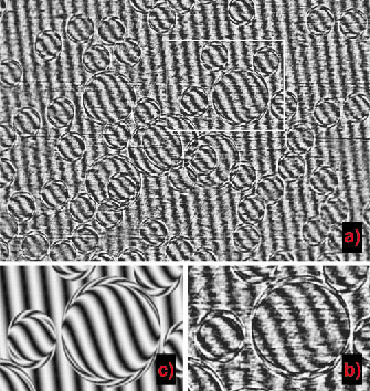
We tested this interferometer on BM5 for several photon energies between 12.4 and 24.8 keV. Polystyrene spheres with 100 and 200 µm diameter were used as well defined phase objects. As can be seen in the interferogram shown in Figure 125a, a change of the orientation of the Moiré-lines is observed, which is directly linked to the difference in phase of the two interfering beams. The obtained interferograms are in excellent agreement with numerical simulations based on a wave propagation algorithm (see Figure 125b, c). This shows that a reconstruction of unknown phase objects from such images is possible.
 |
|
|
As the interferometer is sensitive to any kind of wave front distortion other applications besides phase-contrast imaging can be envisioned. We plan to use the shearing interferometer to map out the quality of optical components such as mirrors situated upstream of the interferometer in the near future.
References
[1] C. David, E. Ziegler, B. Nöhammer, J. Synchrotron Rad. 8, 1054 - 1055 (2001).
[2] U. Bonse and M. Hart, Appl. Phys. Lett. 6, 155-157 (1965).
Principal publication
C. David (a), B. Nöhammer (a), H.H. Solak (a), E. Ziegler (b): Appl. Phys. Lett. 81(17), 3287-3290 (2002).
(a) Laboratory for Micro- and Nanotechnology, Paul Scherrer Institut (Switzerland)
(b) ESRF
partners


European Synchrotron Radiation Facility - 71, avenue des Martyrs, CS 40220, 38043 Grenoble Cedex 9, France.