- Home
- Users & Science
- Scientific Documentation
- ESRF Highlights
- ESRF Highlights 2017
- Structure of materials
- Transmission surface diffraction
Transmission surface diffraction
A new operando method for surface structure determination in an ambient environment has been developed. High-energy photons and transmission geometry are used, allowing the determination of the full in-plane surface structure with a single acquisition. By using a focused beam the local surface properties can be mapped with micrometre spatial resolution.
Processes at material interfaces to liquids or to high-pressure gases are of great interest in many technologically important areas. These include electrochemical energy storage and conversion, heterogeneous catalysis, corrosion, lithographic etching and the deposition of thin films and nanostructures. In these examples the solid material interacts with a fluid, which often leads to complex structural changes at the interface. In order to understand these changes, it is necessary to investigate these structures in situ under operating conditions. Only a few techniques, including synchrotron-based X-ray diffraction, are capable of such experiments.
Recent advances in surface X-ray scattering greatly speed up data acquisition by using high energy photons and large 2D detectors, which allows the measurement of large fractions of reciprocal space at once. Up to now a grazing incidence geometry was used, which has two major disadvantages; firstly, the beam spreads out over a very large area and, secondly, an extremely accurate alignment is required.
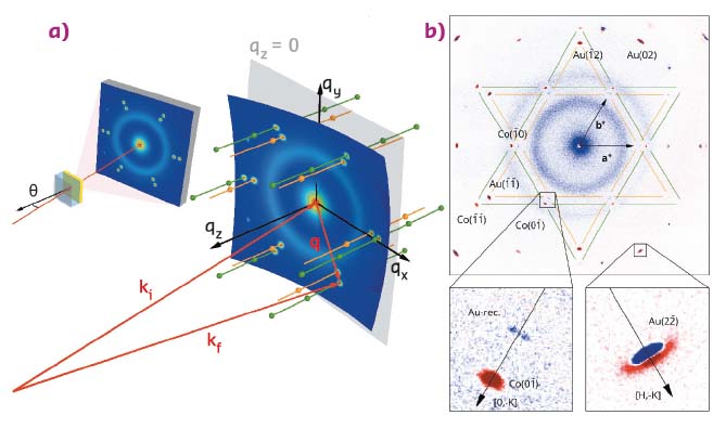
Transmission surface diffraction (TSD), which was developed at ID31, can overcome these difficulties. Here, the high-energy beam is directed perpendicular to the sample surface and passes through the solid sample and adjacent liquid. The scattered intensity is recorded with a large 2D detector located behind the sample (Figure 128a). This arrangement makes sample alignment fast and easy. In this geometry, the Ewald sphere is almost parallel to the surface in the region mapped by the detector, which allows the visualisation of the full in-plane structure of the sample in a single detector image (Figure 128a). By tilting the sample relative to the incident beam by an angle θ, out-of-plane positions along the crystal truncation rods (CTRs), which describe the surface diffraction, can be measured.
 |
|
Fig. 128: a) Scattering geometry of TSD in real space (left) and reciprocal space (right). b) In situ TSD of a thin epitaxial film of Au(111) on Si(111) in 0.1 M NaClO4 + 1.3 mM HCl + 1 mM CoCl2 (40 keV, θ = 4.1°). Shown is the difference between detector images of the bare Au substrate at –0.2 VAg/AgCl and after electrochemical deposition of a 20 monolayer-thick epitaxial Co(001) film at –1.05 VAg/AgCl. A variety of different peaks originating from the change in Co and Au diffraction rod intensity can be seen, where red colours indicate an increase and blue colours a decrease in intensity. |
Figure 128b shows the difference between two detector images of a thin epitaxial Au(111) film on Si(111), before and after the deposition of a 20 monolayer-thick Co film. The image shows the emergence of a hexagonal diffraction pattern due to the growth of an epitaxial Co film. Furthermore, the intensity of the Au rods is altered by the deposition. A change in the Au rod position (Figure 128b) indicates a small change in the Au strain. The disappearance of the characteristic twin peaks near the Au rods (Figure 128b) shows the lifting of the Au surface reconstruction, proving the monolayer sensitivity of TSD.
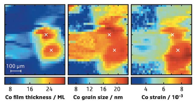
The central advantage of this method is the capability of spatially resolved measurements. Contrary to grazing incidence diffraction, where the beam footprint is usually millimetres in size, the beam footprint in TSD is simply given by the focus of the beam. Figure 129 shows maps of different surface properties of an 8 nm-thick epitaxial Co film deposited on Au(111)/Si(111) obtained in solution. The maps were created by recording 31 × 31 TSD images on a 600 × 700 μm2 grid, using a beam size of 10 × 20 μm2 and a photon energy of 40 keV. The tilt angle θ was 4.1°, such that a Co Bragg peak was directly on the Ewald sphere. Co film thickness, in-plane grain size and in-plane strain were determined by fitting the Co peak intensity, width and position at each of the 961 TSD detector images.
 |
|
Fig. 129: TSD real space mapping (600 µm x 700 µm) of Co films on Au(111) in 0.1 M NaClO4 + 1.3 mM HCl at -1.05 VAg/AgCl. Shown are film thickness (left), the in-plane grain size (middle) and in-plane strain (right) determined from the Co (-1 0) CTR. |
With its mapping capabilities, TSD can provide information about the heterogeneity of the surface structure that cannot be obtained with any other method. Sample alignment for TSD is simple and fast and the images are intuitive to read since they are similar to Laue diffraction and LEED. This also makes TSD a great tool for inexperienced users of synchrotron radiation.
Principal publication and authors
Transmission Surface Diffraction for Operando Studies of Heterogeneous Interfaces, F. Reikowski (a), T. Wiegmann (a), J. Stettner (a), J. Drnec (b), V. Honkimäki (b), F. Maroun (c), P. Allongue (c) and O.M. Magnussen (a), J. Phys. Chem. Lett. 8, 1067-1071 (2017); doi: 10.1021/acs.jpclett.7b00332.
(a) Institut für Experimentelle und Angewandte Physik, Christian-Albrechts-Universität zu Kiel (Germany)
(b) ESRF
(c) Physique de la Matière Condensée, Ecole Polytechnique (France)
partners


European Synchrotron Radiation Facility - 71, avenue des Martyrs, CS 40220, 38043 Grenoble Cedex 9, France.