- Home
- Users & Science
- Scientific Documentation
- ESRF Highlights
- ESRF Highlights 2017
- Structure of materials
- Cobalt-based catalyst structure evolves according to particle size during FTS
Cobalt-based catalyst structure evolves according to particle size during FTS
The combination of in situ X-ray diffraction computed tomography and pair distribution function computed tomography has been used to study a 3 mm Co/γ-Al2O3 catalyst for Fischer-Tropsch synthesis. This combination of techniques is very powerful for unravelling the complex Co nanoparticle phase evolution to obtain a more complete understanding of the structure-activity relationships in this catalytic system.
Fischer-Tropsch synthesis (FTS), is a catalytic process that produces long chain alkanes, alkenes or alcohols using synthesis gas (CO/H2 mixture) and is considered one of the more viable routes to replace diesel with ultraclean fuels [1,2]. A popular industrial catalyst for this process comprises cobalt (Co0) dispersed as small nanoparticles on a microporous/mesoporous structure or oxide support (Al2O3, SiO2 and TiO2). Co0 particles are believed to be the primary active sites as they are present pre-, post- and during FTS and are thought to be necessary for high product selectivity.
The state of Co under operational conditions and in a deactivated catalyst has been of much interest and observations show an ‘evolution’ of the Co nanoparticle structure, including sintering, dispersion, a decrease in scattering density thought to be due to interstitial C species, as well as oxidation to form cobalt oxides; all of which in extreme cases leads to a loss in activity [3]. Previous in situ and operando studies utilise catalysts in powdered form but industrial catalysts should preferably be studied in their entirety to fully understand the importance of structure with function. Furthermore, today, spatially resolved chemical imaging processes as a function of time (referred to as 5D sample interrogation: 3 spatial dimensions, time and the spectral dimension) allow for a more detailed appreciation of the complex behaviour of real materials.
This work used in situ X-ray diffraction computed tomography (µ-XRD-CT) and pair distribution function computed tomography (µ-PDF-CT) at ID15A to study a 3 mm Co/γ-Al2O3 catalyst to understand the evolution of the Co environment during reduction and under real FT conditions (CO/H2, ratio 1:2). The evolution of the cobalt phases was followed to determine the nature of the active species under process conditions as well as to lend insight into how to design a better performing catalyst.
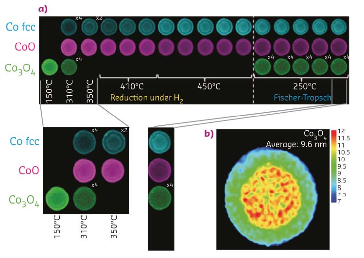
Time and spatially resolved XRD-CT data are given in Figure 134 and show a gradual evolution of Co crystalline phase from Co3O4 → CoO → Co fcc metal during the pre-reaction reduction treatment in dilute flowing H2. During reduction, Co spatial distribution is broadly retained irrespective of Co phase evolution with time/temperature. The catalytically relevant Co fcc metal phase follows a ‘shrinking core’ model for its formation but, interestingly, scattering intensity increases, particularly at the sample edge; this is suggestive of facile Co formation at the sample edge where oxide phases first encounter H2. During FTS, the Co fcc phase reduces in intensity, particularly at the edge of the particle where both CoO and the Co3O4 phase reform. The middle of the catalyst pellet remains largely unchanged in comparison. These behavioural differences reflect a difference in particle size of the Co-containing phases present at the beginning.
 |
|
Fig. 134: a) Reconstructed 2D integrated reflection intensity maps for Co3O4 (220), CoO (200) and fcc Co (111) observed under reduction and during FTS conditions as a function of temperature and time. Values depicted in the right-hand corner (particularly Co3O4) illustrate how integrated intensity has been multiplied to enable plotting on a common intensity axis. b) Co3O4 (nano)particle size distribution map recorded at 150 °C during reduction in H2. |
Imperfections in the catalyst preparation process cause a range of species to be observed. These include two types of Co3O4 particles present at the fresh catalyst (Figure 134b) – well dispersed particles that interact strongly with the γ-Al2O3 support and poorly dispersed particles that don’t. The former, when ≤ ~ 6.5 nm, cannot be fully reduced and remains as CoO during reduction treatment, whereas the latter reduces more easily. Also, µ-XRD-CT and µ-PDF-CT suggest the majority of aggregated particles are found at the edge of the sample and in the central 2.5 mm diameter of the pellet. The smaller, more numerous nanoparticles at the edge appear to reduce more quickly than the larger particles on the inside. However, these particles oxidise more readily on switchover to FTS since average metallic fcc Co particle size increase is observed at the periphery.
The results illustrate the challenge of creating a structured FTS-active Co/γ-Al2O3 pellet, since various Co-containing phases were detected in the sample. However, it demonstrates how µ-XRD-CT and µ-PDF-CT can put phase evolution changes into spatial context, which isn’t possible via single point measurement. These techniques should eventually allow all industrial catalysts to be chemically imaged in situ for a more thorough evaluation of catalytic performance.
Principal publication and authors
Real-Time Scattering-Contrast Imaging of a Supported Cobalt-Based Catalyst Body During Activation and Fischer Tropsch Synthesis Reveals Spatial Dependency of Particle Size and Phase on Catalytic Properties, P. Senecal (a), S.D.M. Jacques (b), M. di Michiel (c), S.A.J. Kimber (c), A. Vamvakeros (a), Y. Odarchenko (a), I. Lezcano-González (a),
J. Paterson (d), E. Ferguson (d) and A.M. Beale (a), ACS Catal. 7, 2284-2293 (2017); doi: 10.1021/acscatal.6b03145.
(a) Research Complex at Harwell & University College London (UK)
(b) University of Manchester, Manchester (UK)
(c) ESRF
(d) BP International Ltd (UK)
References
[1] S.S. Ail and S. Dasappa, Renew. Sust. Energ. Rev. 58, 267 (2016).
[2] A.Y. Khodakov et al., Chem. Rev. 107, 1692 (2007).
[3] J.J. Herbert et al., Cat. Sci. Tech. 6, 5773 (2016).
partners


European Synchrotron Radiation Facility - 71, avenue des Martyrs, CS 40220, 38043 Grenoble Cedex 9, France.