- Home
- Users & Science
- Scientific Documentation
- ESRF Highlights
- ESRF Highlights 2016
- Enabling technologies
- RF Fingers for the ESRF-EBS storage ring
RF Fingers for the ESRF-EBS storage ring
The ESRF-EBS storage ring features new vacuum chamber profiles with reduced aperture. Radio frequency (RF) fingers are a key component to ensure good vacuum conditions and reach the best possible machine performance. A more compact, more robust and more reliable design has been produced for the new storage ring.
To absorb chamber-to-chamber misalignment and thermal expansion, for instance during bake-out, bellows are used to inter-connect a large number of chambers along the ring circumference. These bellows, however, are seen as resonant cavities by the beam hence breaking the geometrical continuity of the beam pipe and leading to degraded vacuum and stability. The continuity is restored by electrically shielding the bellows from the beam using so-called RF fingers which consist of conductors matching the vacuum chamber profile and connecting the beam pipes on either side of the bellows. The RF fingers are meant to absorb mechanical movements while providing the best possible electrical and geometrical continuity: designing such a device is therefore far from trivial since many aspects have to be carefully optimised.
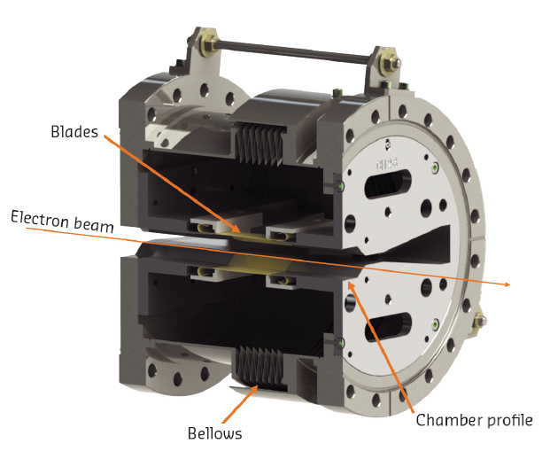
The new omega-shaped chamber profile is incompatible with the present RF finger design if geometrical continuity is to be enforced. Therefore, a dedicated in-house design based on new concepts was devised for the ESRF-EBS ring. Figure 149 shows the final design, which is the result of several iterations to optimise its beam coupling impedance and mechanical properties.
 |
|
Fig. 149: RF Finger placed in a bellows. |
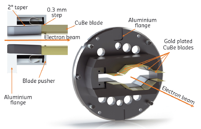
The first step was to ensure that the cavity formed by the bellows was properly shielded from the beam. This was achieved by adding four blades (two top and two bottom) on either side of the initial design, thus extending the horizontal dimensions of the RF fingers as seen in Figure 150. If the bellows are invisible to the beam then the beam coupling impedance is given only by the geometrical discontinuities of the inner volume. In this case, it is the steps and taper angle at the entrance and exit of the RF fingers, which can be seen in Figure 150. The step height was fixed at 0.3 mm for mechanical criteria and the only parameter left for optimisation was the taper angle, a good compromise was found with a reduction of the taper angle from 5° to 2° leading to a reduction of the beam coupling impedance by a factor 4. This result was found satisfactory as the resulting full contribution of the RF fingers to the total impedance of the machine became significantly smaller than the contribution of beam pipes themselves.
 |
|
Fig. 150: RF Finger cut view. |
The shielding blades (the RF fingers) are made with copper-beryllium (CuBe2) and the flange parts with an aluminum alloy. Copper-beryllium is a high resistance, highly conductive alloy, ideal for the RF finger’s function, whereas an aluminium alloy is easier to machine to achieve the desired complex shape of the flange part.
A thorough structural mechanical finite element analysis (FEA) was performed to validate the new RF finger design with respect to mechanical stress and the necessary electrical contact. At the same time, the FEA served to study the design optimisation possibilities considering the specific component requirements. A parameter study of three key geometrical dimensions was carried out to gain knowledge about their influence on the performance and mechanical safety. One of the parameters that varied in the course of this analysis was the blade thickness of the fingers.
In the structural analysis, the new component concept generally showed good compliance for the defined requirements as the electric contact quality is very high. The latter mainly depends on the contact force which is comparably high for all parameter variations and of at least 1.5 N per blade. This contact should be sufficient as the image current on the surrounding walls is most likely a surface current. In all load cases and movements, the blades are in good contact at the relevant contact position.
The required flexibility can be safely guaranteed. We considered different blade thicknesses. While thinner blades tend to be more flexible, their contact force drops but the safety margin of occurring mechanical stress is higher. The use of thinner blades that lead to a lower contact force could be a solution to reduce friction-caused wear while maintaining a very good electric contact. The safety factor between mechanical stress and the elastic limit is at least 1.2 for the analysed parameter variations during a relative flange movement of 2 mm between both flanges; this was considered as sufficiently flexible. Small plastic deformations in the flange part turned out to be tolerable and the component’s functionality can also be maintained.
The new design, patented, will be used on all chamber profiles, high, low and straight section profiles. For the RF performance, a test in the current machine is foreseen in March 2017.
Authors
T. Brochard, P. Brumund, L. Goirand, J. Pasquaud and S. White.
ESRF
partners


European Synchrotron Radiation Facility - 71, avenue des Martyrs, CS 40220, 38043 Grenoble Cedex 9, France.