- Home
- Users & Science
- Scientific Documentation
- ESRF Highlights
- ESRF Highlights 2014
- Accelerator and X-ray source
Accelerator and X-ray source
The Accelerator and Source Division (ASD) is in charge of the production of synchrotron light from the ESRF’s 6 GeV storage ring. We have continued our efforts to ensure reliable operation during 2014. Indeed, during the year, 5399.20 hours of beam was delivered, representing an accelerator availability of 99.11% and beating the all-time ESRF record of 99.04% in 2009.
As well as providing beam to users, with 2014 marking the end of Phase I of the Upgrade Programme, the Division has completed or is in a very advanced stage of completion of major upgrades of several subsystems of the accelerator complex, including:
- Upgrade of the RF system with solid state amplifiers (completed)
- Development and installation of new higher order mode (HOM)-damped cavities (completed)
- Development and installation of improved electron beam position monitoring system and a fast orbit feedback system (completed)
- Extension of the straight sections from 5 m to 6 m (completed)
- Installation of canted straight sections (completed)
- Installation of one 7 m straight section (completed)
- Implementation of top-up mode capability (in progress)
This year was also a crucial year for the future of the Phase II Accelerator Upgrade, and a lot of time was dedicated to presenting our ideas, studies and designs to the Accelerator Project Advisory Committee (APAC), which was held in January, May, September and October. Following positive reports from the APAC in May, the project was approved and launched by the ESRF Council in June 2014. The upgrade will see the implementation of a new lattice for the storage ring to reduce the natural horizontal emittance from 4 nm to about 134 pm, thus greatly increasing the brilliance and coherence of the beam.
In addition to our work on Phase I and Phase II, we also hosted the 22nd annual European Synchrotron Light Source (ESLS) workshop in November. Thirty-five representatives from fifteen European light sources spent two days at the ESRF discussing the status of their institutes operational performance as well as future upgrade projects. We were pleased to note that the accelerator lattice concept developed at the ESRF is being adopted by many other world-leading synchrotron facilities.
After a busy but fruitful year, we entered the execution phase of the Phase II Upgrade Programme on 1st January 2015 and work on the project is now in full swing.
P. Raimondi
Beam parameters of the storage ring
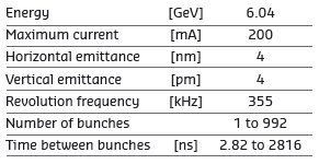
Table 1 presents a summary of the characteristics of the storage ring electron beam.
 |
|
Table 1: Principal characteristics of the electron beam. |
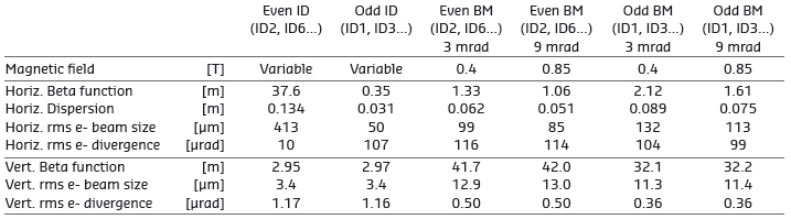
Table 2 gives the main optic functions, electron beam size and divergence at various source points. For insertion device source points, the beta functions, dispersion, sizes and divergences are calculated in the middle of the straight section. For bending magnets, two representative source points have been selected for each type (even or odd cell number) of magnet, corresponding to magnetic fields of 0.4 T and 0.85 T. These points differ by the observation angles, of respectively 3 and 9 mrad from the entrance of the magnet.
 |
|
Table 2: Beta functions, dispersion, rms beam size and divergence at the various source points. |
Electron beam profiles are Gaussian and the size and divergence are presented in terms of rms values. The associated full width at half maximum sizes and divergences are 2.35 times higher. Horizontal electron beam sizes and divergences are given for the multibunch filling modes and apply to almost all filling patterns, except when the current per bunch is larger than 4.5 mA, for which a slightly larger size and divergence are attained because of the increased energy spread of the electron beam.
Vertical electron beam sizes and divergences are given for a vertical emittance of 4 pm, which is now the standard for 2 x 1/3 and 7/8+1 filling modes. The vertical sizes and divergences are about 1.4 times larger in uniform filling mode (due to ion effects, which are partially corrected by the use of a vertical bunch-by-bunch feedback). To increase the lifetime of the stored beam, the vertical beam sizes and divergences are deliberately increased by about a factor of 4 in the 16-bunch, 4-bunch and hybrid filling patterns.
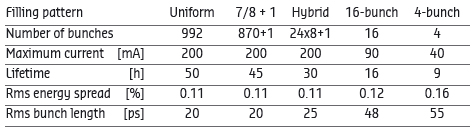
The lifetime, bunch length and energy spread mainly depend on the filling pattern. These are given in Table 3 for a few representative patterns. Note that in 16-bunch and 4-bunch filling patterns, the energy spread and bunch length decay with the current (the value indicated in the table corresponds to the maximum current). The bunch lengths are given for the usual radiofrequency accelerating voltage of 9 MV (8 MV for 16-bunch and 4-bunch).
 |
|
Table 3: Current, lifetime, bunch length and energy spread for a selection of filling modes. |
Summary of accelerator operation
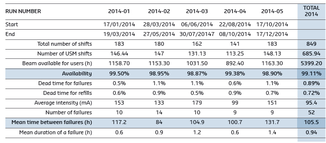
Last year was a record-breaking year for accelerator operation, seeing 5399.20 out of 5487.5 planned hours of beam delivered to Users in 2014 (excluding shifts for radiation and personal safety system tests). This excellent figure represents an accelerator availability of 99.11%, which beats the all-time ESRF record of 99.04% in 2009. This was achieved through a rapid resolution of failures, of which only a few were significant long failures. The longest of these was in May and lasted just over four hours.
 |
|
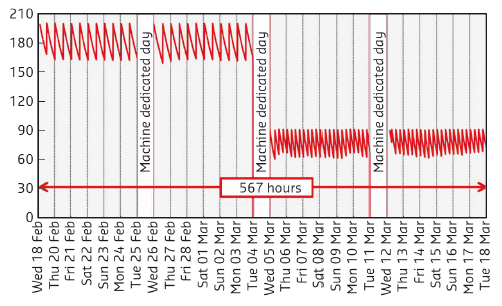
Fig. 158: Uninterrupted beam delivery for 567 hours in 7/8+1 and 16-bunch filling modes during weeks 5, 6, 7 and 8 (RUN 2014-01). |
Similarly, the mean time between failures (MTBF) of 105.5 hours is the second best MTBF ever obtained at the ESRF (the record is 107.8 hours in 2011). In April, during the second run of the year, six beam trips during the same week reduced the MTBF. This was due to an unfortunate series of events. Once these problems had been solved, a noticeable absence of repetitive events (especially during Runs 1, 3 and 5 when the MTBF greatly exceeded 100 hours) resulted in 14 out of 37 weeks where beam was delivered without any interruptions, including one period of four weeks (see Figure 158) and two periods of 288 hours (i.e. two consecutive weeks) without a single beam interruption. A summary of operation is presented in Table 4.
 |
|
Table 4: Overview of storage ring operation in 2014. |
Filling patterns
The distribution of filling modes (Figure 159) has not drastically evolved over the last four years, since the 7/8+1 filling mode was introduced. This mode remains the best compromise for users who need intensity and/or time-structure. The uniform mode remains mainly for the specific experiments on one beamline.
During machine-dedicated time, several shifts were carried with participation of the beamlines to assess top-up in 16-bunch mode, testing refills every 10, 20 and 30 minutes. Many scientists expressed their enthusiasm thanks to the excellent results obtained. More details are presented in a later section.
|
|
|
Fig. 159: Distribution of filling modes in 2014. |
Completion of the technical design study for the new storage ring
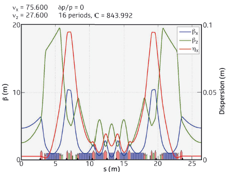
In 2014, the ASD completed the technical design study (TDS) of the Phase II Accelerator Upgrade. The upgrade is focused on greatly improving the brightness of the source by decreasing the natural horizontal equilibrium emittance of the storage ring from the current 4 nm to about 134 pm. This will be possible by replacing the present 32 double-bend achromat arcs with a much more compact lattice based on a hybrid 7-bend arc achromat (Figure 160). The smaller emittance, together with a shorter-period, smaller-gap undulators and new beamline optics, optimised to take full advantage of the new source, will allow a general improvement in performance by a factor of 100 or more.
 |
|
Fig. 160: The ESRF hybrid multi-bend achromat (HMBA) lattice design. |
The sources for the bending magnet beamlines will be replaced by three-pole wigglers, resulting in a comparable increase in brightness and flexibility of the X-ray spectra for these beamlines too. The lattice and the engineering designs are well advanced and the magnetic designs are already at the prototyping stage. A prototype octupole was delivered in October 2014 (see Figure 161). Two prototypes of the permanent magnet dipoles with longitudinal gradients have been constructed and a third is planned for 2015. A high-gradient quadrupole prototype is currently under construction and prototypes for a combined dipole-quadrupole and a sextupole are foreseen for 2015. The first magnetic designs for the correctors have been completed and the engineering designs will be done in 2015.
 |
|
Fig. 161: The prototype octupole for the new lattice, delivered in October 2014. |
In May 2014, the Accelerator Project Advisory Committee (APAC), appointed by the Council, reviewed and produced a very positive report on the overall feasibility of the project. The TDS, together with their report was submitted to the June meeting of the Council, which subsequently gave its approval to the project. The execution phase was officially launched on 1st January 2015.
Permanent magnet dipoles for the accelerator upgrade
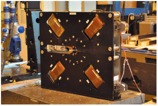
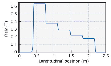
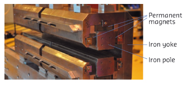
The new magnet lattice for the accelerator upgrade includes 128 dipoles with longitudinal field gradients contributing to the reduction of the horizontal emittance of the electron beam. The use of permanent magnet technology was found to be suitable for building these dipoles for compactness and economical reasons. Each dipole magnet consists of a series of five short modules with different field amplitudes, ranging from 0.65 T to 0.17 T (see Figure 162).
 |
|
Fig. 162: Typical magnetic field along a dipole with a longitudinal field gradient. |
The Sm2C017 permanent magnet material was chosen to ensure adequate temperature stability and long-term stability with respect to radiation-induced demagnetisation. The development of permanent magnet structures was initiated in 2013-2014 with the construction of several types of modules. Each module has a length of 350 mm and a transverse size of 190 mm (horizontal) and 240 mm (vertical) with a typical weight of 85 kg. The magnetic structure is based on a C-shape design with solid iron poles and a yoke driving the magnetic field from permanent magnets in the 25 mm gap. Figure 163 shows an assembly of two modules under study. The magnetic measurement results are in very good agreement with the simulation.
 |
|
Fig. 163: Prototype dipoles with longitudinal field gradient under study (two modules). |
Progress in the top-up operation project
To reduce the heat load variation on the beamline optics, the implementation of top-up operation is under preparation. This mode of operation will be beneficial for the 16-bunch mode by reducing the current variation and also by allowing delivery at low vertical emittance. A new cleaning technique has been developed for this project and is now routinely used during user service mode (USM) for the 16bunch and hybrid modes. This reduces the strong vertical blow-up just after injection from 2 nm to only a few pm. The development of bunch cleaning in the booster is progressing and will benefit from the upgrade of the injector, in particular, the new booster power supply system operating at 4 Hz, which is under development for the dipole and quadrupole magnets.
 |
|
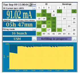
Fig. 164: Synopsis of eight hours of top-up tests with beamlines in September 2014. |
Top-up in 16-bunch mode has been tested successfully (Figure 164). The reliability of the storage ring was validated with 90 mA average current in 16bunch mode, refilled every 10 minutes over a period of several hours, with no disturbance; all parameters were even more stable in this configuration. Radioprotection aspects are satisfactory (injection is routinely performed with the front end open) but a formal agreement from the authorities for such operation in USM is still needed. Large horizontal orbit perturbations are still being induced during injection, mainly by the injection kickers and injection septa. Solutions using feed-forward corrections have been successfully developed and should be implemented for routine operation (see dedicated paragraph). An injection sequencer has been developed in order to automatically manage the equipment and to optimise electrical consumption. Using this tool, injection is now done in top-up in less than 30 seconds.
The top-up frequency is a crucial parameter for this project. The first top-up tests with users at the beamlines were carried out in September 2013 and May 2014 in 16-bunch mode, with a refill every 5, 10, 20 and 30 minutes. The main feedback from the beamlines was that it had not been possible to move the mechanics during the top-up sequences, preventing them from taking maximum advantage from top-up operation. This was due to a restriction on an ID device server, which was then removed in time for the next tests.
In September, a third top-up shift – also in 16-bunch mode – was carried out with 23 beamlines. This time it had been possible for the beamlines to move their mechanics and the lowest gap of 6 mm was obtained at ID09 and ID11 in-vacuum devices, while ID15 obtained 6.5 mm. The beamline feedback was positive, showing a general improvement in the stability of all the X-ray beam parameters. The beamlines could be operated without interruption during injections and were unable to detect the exact moment when refills had been carried out.
Nevertheless, detailed analysis and tests still have to be completed for the most sensitive beamlines. Further user tests are planned for early 2015. There remains much to do in order to ensure reliability of equipment before top-up operation can be put into routine service but the benefits for most users are clear.
New storage ring BPM prototypes tested with beam
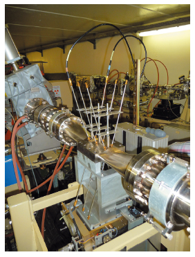
The development of 6 mm-button UHV feed-throughs is making very good progress; a total of 27 buttons were delivered in the spring and tested successfully. During the August 2014 shutdown, a test beam position monitor (BPM) chamber was installed in the ID25 straight section (Figure 165). Three BPMs were connected to the Libera BPM electronics and the test BPM chamber itself placed on a motorised translation table allowing +/-3 mm displacement in both planes, to enable RF signals to be checked with stored beam and to carry out detailed verification of the beam position measurements obtained. A second chamber with different buttons will shortly be installed and tested.
 |
|
Fig. 165: The test BPM chamber installed at ID25. |
New booster bpm electronics
Following the goal to modernise the 25-year-old electronics for the RF signal acquisition and processing of the booster BPM system, two prototypes, called Libera Spark, have been tested under various beam filling modes in the booster and they have shown their potential for precise beam position monitoring. After satisfactory testing, a contract for the delivery of a further 81 units was signed and these were delivered in November 2014. The installation of these Sparks in the booster has now started and 10 units were successfully commissioned in December. The full conversion to the new BPM system is expected to be finished by the end of February 2015. An agreement has been reached on specifications and a price for an advanced version of this device that opens up various applications in the injector and the storage ring.
New Vertical beam halo monitor
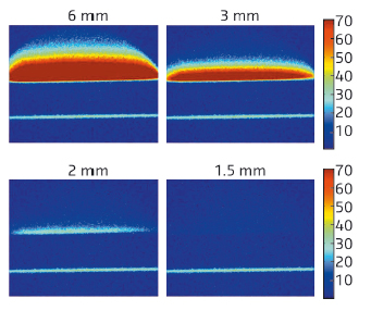
The halo monitor measures the electron population along the vertical beam profile at 0.5 mm to 6 mm from the central core of the electron beam, using X-rays emitted from the first dipole in cell 7. Following initial commissioning at the beginning of the year, the halo monitor was further optimised with more rigorous lead shielding for its detector and the choice of CMOS camera technology, which has greater resistance to radiation. The tungsten blade has also been modified to give more calibration possibilities. A device server records halo measurements at a frequency of 1 Hz and stores them in a database (Figure 166). Such recordings show the very strong sensitivity of this diagnostic device to vacuum conditions and to any variation of Touschek scattering conditions. It is a new and novel addition to our range of diagnostic instruments dedicated to electron beam loss phenomena.
 |
|
Fig. 166: Images from the halo monitor for four vertical scraper positions. In the lower part of each image, one can observe that the beam core is shielded while the halo signal disappears progressively. |
New picosecond time-resolution streak camera
The new visible light streak camera was delivered to the ASD optical laboratory in January 2014. The results obtained from various tests were satisfactory and in line with the theoretically predicted shortest bunch length at zero bunch current. Since its installation, the Streak camera has been used in several MDT studies, such as HOM instability and also for beam dynamics studies relating the RF voltage to beam phase, bunch length and lifetime. After initial setup for each experiment, the streak camera can be controlled and read from the control room.
New bunch cleaning method for the booster
A new method of time-gated cleaning was implemented in 2013, using the bunch-by-bunch feedback system. However, since cleaning is performed after injection into the storage ring, it won’t be compatible with the future top-up mode of operation, as the time interval between injections will become much smaller. Therefore, in 2014, a new system was implemented to perform bunch cleaning 5 to 10 milliseconds after injection in the booster. This has been upgraded by the addition of a system generating the excitation frequency of the parasitic bunches more accurately. Now that the transverse resonant frequency of the beam is tracked precisely, the cleaning efficiency should be stable at each injection. Measurements taken in the autumn of the efficiency of the booster cleaning showed that adequate cleaning is generally achieved for most injection shots. Future work will aim to increase the reproducibility of the system.
Damping of the horizontal oscillation of the storage ring stored beam caused by injection
The firing of the pulsed magnets of the injection system (kickers and septum) is the cause of horizontal and vertical transient orbit distortion or beam position oscillation. Various factors contribute to this disturbance including non-closure of the injection bump during kicker rise and fall, a slight tilt of the kickers, septum magnet field leakage and asymmetry. The horizontal disturbance is the largest, but is expressed in the relative increase of the beam emittance, whereas the vertical disturbance is more significant since the vertical nominal emittance is much smaller. Solutions are underway to tackle each source of disturbance.
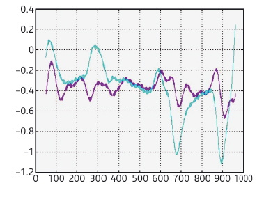
We have implemented a system that damps the horizontal betatron oscillation by applying a correction signal over nine turns using a 0.6 MHz bandwidth magnet driven by a 400 W amplifier. The system was tested at the end of 2013 and proved to be effective, dividing the amplitude of the horizontal betatron oscillation induced during the rise and fall time of the kickers by three (Figure 167).
 |
|
Fig. 167: Non-damped (purple) versus damped (blue) horizontal oscillations over turn 7 to turn 10 after injection, for all bunches, showing the effect of the feed-forward damping. |
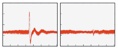
At the end of 2014, an orbit correction system cancelling the horizontal orbit distortion caused by the septum leakage was also implemented, using a set of fast corrector magnets and amplifiers that were originally part of the old fast orbit correction system. A signal with the same shape as the beam position signal recorded when the correction was not active was used to drive the amplifier input in a feed-forward scheme. The first test of the system demonstrated a very effective cancellation of this orbit distortion (Figure 168). A similar set of vertical correctors was added during the December 2014 shutdown and the system will be operated in USM in 2015.
 |
|
Fig. 168: Effect of the septum field leak on the horizontal beam position without (left) and with (right) the orbit correction system activated. Scale: Vertical: 0.5 mm/div, Horizontal: 10 ms/div. |
We aim to suppress the vertical betatron oscillation due to the kickers’ tilt by mechanically trimming the tilt of the kickers according to the result of turn-by-turn position measurements done following the firing of the kickers. A first set of tilt corrections will be applied during the shutdown in January 2015.
Update on the new HOM-damped cavities in the storage ring powered by 150 kW RF solid state amplifiers
In 2013, three new RF HOM-damped cavities were installed in cell 23, the last being put in place during the December shutdown and powered in January 2014. The first two cavities performed well throughout 2014. They were operated in USM at the nominal voltage of 0.5 MV with 80 kW input power at a stored beam current of 200 mA. During machine studies, these cavities were tested with up to 150 kW incident power by increasing their voltage to 0.65 MV and adjusting their phase to increase their beam loading. Following the discovery of an air leak in the third cavity, it was removed from the ring for repair in December 2014. The manufacture of 12 additional HOM-damped cavities by RI is progressing well and the delivery is foreseen during the course of 2015.
The four 150 kW solid state amplifiers (SSAs) installed in the booster in 2012, and the three SSAs installed in the storage ring in 2013, are all performing well. In October 2014, the supplier retrofitted the four booster SSAs with non-flame-propagating cables, bringing them in line with the three storage ring SSAs.
The implementation of the in-house 75 kW prototype RF SSA, which uses a cavity combiner to combine the power from 132 ESRF-developed 700 W RF power modules, is in progress. This came within the remit of work package WP7 of the EU/CRISP project, which ended in September 2014. Over the course of the project, it was decided to develop an integrated system comprising fully planar RF circuits that are coupled directly to the cavity combiner instead of connecting existing RF modules available from industry by means of coaxial cables. This resulted in an extremely compact solution that will allow cost effective industrial production. A 12 kW prototype with 18 connected modules was successfully tested, and power tests of the 75 kW prototype are scheduled for the second half of 2015.
ID straight sections
The required undulator segments for the upgrade of ID01 have been installed and are in operation. The new 2.5 m-long helical undulator will be installed in March 2015 in the ID32 straight section. Most of the work is now focused on ID31 and ID15. A high-performance cryogenic permanent magnet undulator is under construction at ID31. The undulator will be installed in the middle of the 5 m-long straight section to reach a minimum gap of 4.5 mm. Its installation will take place before mid-2015. At ID15, the straight section will be modified with a canting scheme in 2015. A required short, high-field wiggler has been designed and the associated components are under procurement. The modification of the straight section and a new insertion device layout will be completed before the end of 2015.
partners


European Synchrotron Radiation Facility - 71, avenue des Martyrs, CS 40220, 38043 Grenoble Cedex 9, France.