Scientific Examples
The white-beam high energy hutch EH2 is considered a strategic resource, as the ESRF is the only place in the world where this facility is available. The continuous spectrum from the wiggler has two main advantages, its very high (energy integrated) intensity, and the enormous penetrating power of very hard x-rays. These two factors were crucial in the examples described below.
Ultra fast white beam diffraction
The thick shielding present in EH2 means that high energy white beam experiments are feasible. When the wiggler is used this means that a continuous spectrum up to ca. 500 KeV is present. The incident intensity integrated over all energies is also extremely high, which allows ultra fast Laue experiments to be performed. This was exploited by Mirihanage et al, who collected data during the solidification of weld pools. The total experiment time was 1.5 s and diffraction data were collected at a frame rate of 1 kHz using an image intensifier coupled to an imaging camera.
The data were processed in terms of integrated diffraction spot intensities and angular positions to allow for information to be extracted on the growth of individual columnar crystals, overall solid fraction evolution and accompanying grain rotation dynamics As shown below, correlation between the temporal evolutions in integrated intensities, grain motions and 2D diffraction spot areas pointed towards columnar crystal tilting at their attaching roots as the predominant mode of grain motion, and, by further data analysis, the tilting motion could be expressed in terms of metric velocities at the crystal tips. When growth and tilting rates at the columnar tips are compared, crystal growth velocities and tilting velocities are found to be of the same order of magnitude, especially in the earlier stages of solidification. Thus, solute pile-up ahead of the columnar front should be effectively removed not only by strong convection, but also by tilting, such that growth at this stage should be substantially different from situations where only melt convection and diffusion are present.
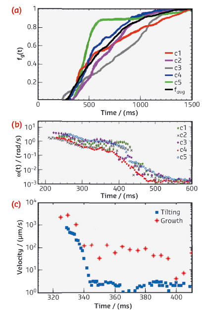
Fig. 1: a) Columnar (c) crystal volume evolution, c1-c5 denotes 5 different crystals, and favg presents the overall solid volume fraction. b) time-evolution of angular velocities for crystals c1-c5. c) evolution of growth and tilting velocities for one representative columnar crystal. See: W.U. Mirihanage (a), M. Di Michiel (b), A. Reiten (a), L. Arnberg (c), H.B. Dong (d) and R.H. Mathiesen (a), Acta Materialia 68, 159-168 (2014).
Strain scanning
Relatively large components can be analysed non-destructively using energy dispersive x-ray diffraction. The high energies available mean that path lengths of the order of cm are accessible in e.g. Al based alloys. In a typical experiment, Ge based detectors are placed in horizontally and vertically offset positions as shown below for the example of crack tip mapping. The incident beam may then be collimated down to 50 x 50 µm, giving high spatial resolution.
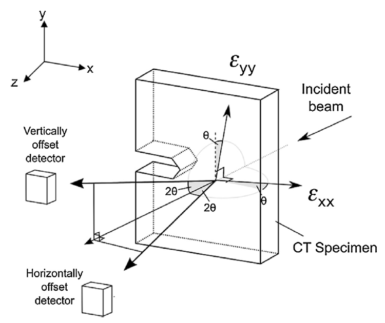
In the scientific example described here, this technique was used to investigate the effect of overloading on fatigue crack growth. The sample was a 12 mm thick hot pressed sample of an Al-Li aerospace alloy. The measured and fitted elastic strain fields from the two detectors are shown below.
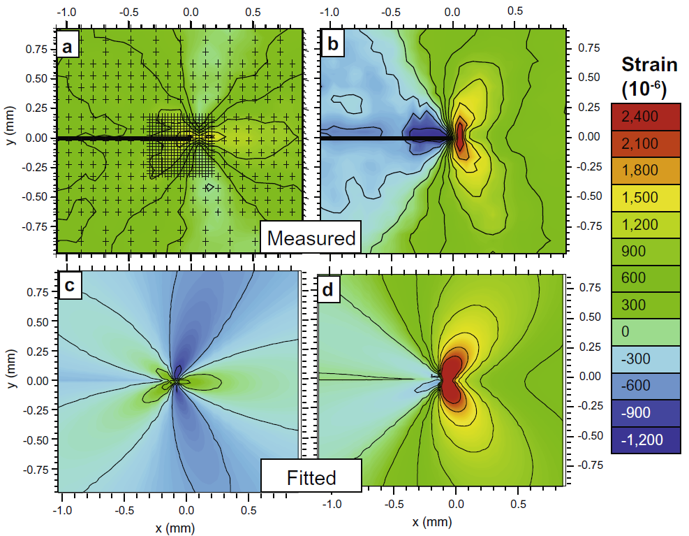
Fig 2. The raw measured data (top) and best fit (bottom) elastic strain fields. For (a) and (c) the crack growth and (b) and (d) the crack opening directions. See: A Steuwer et al, Acta Materialia, 58, 4039-4052 (2010)
More conventional monochromatic beam diffraction experiments are also possible. This technique is complimented by a suite of sample environment including stress rigs from Instrom such as the ETMT. Using the refractive lenses installed in the optics hutch, the beam may be focused down to ca. 50 µm in the vertical and horizontal direction for mapping experiments
partners


European Synchrotron Radiation Facility - 71, avenue des Martyrs, CS 40220, 38043 Grenoble Cedex 9, France.