- Home
- Users & Science
- Find a beamline
- Electronic structure, magnetism and dynamics
- ID20 - Inelastic Scattering I
- Beamline Characteristics
Beamline Characteristics
General optical layout
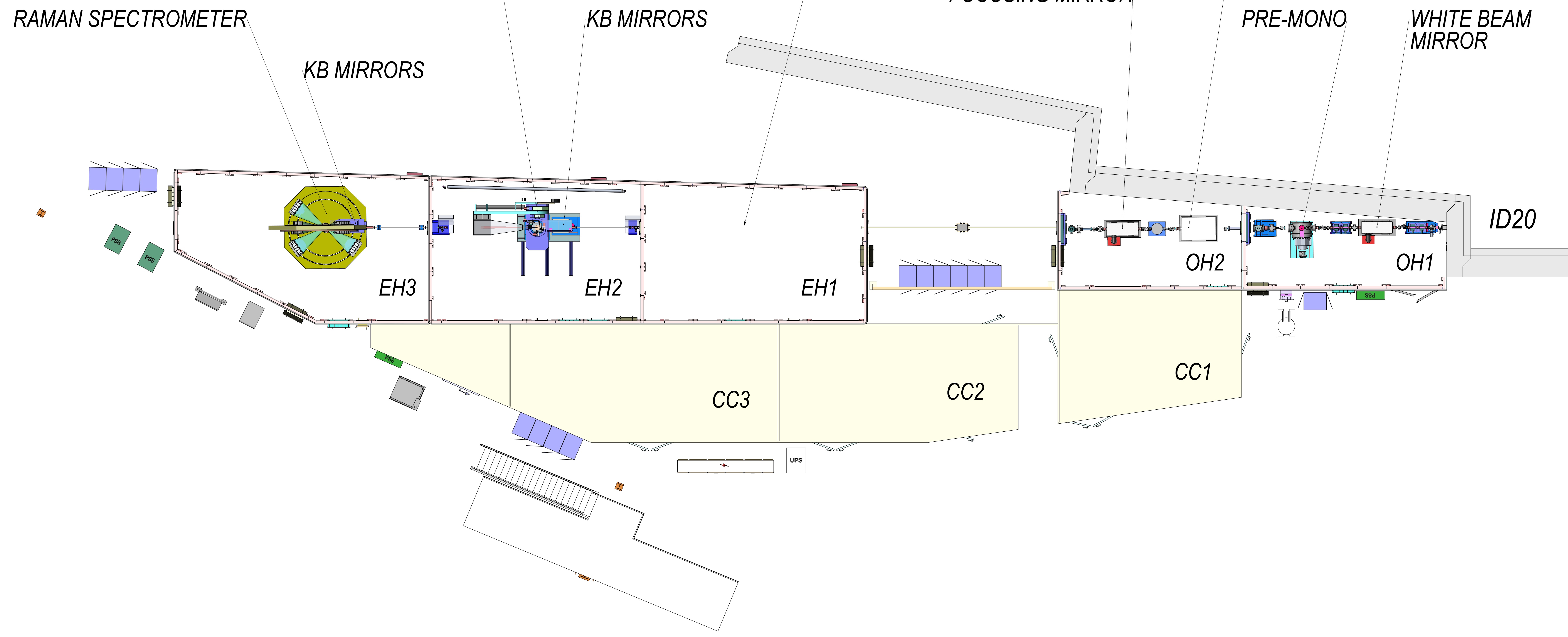
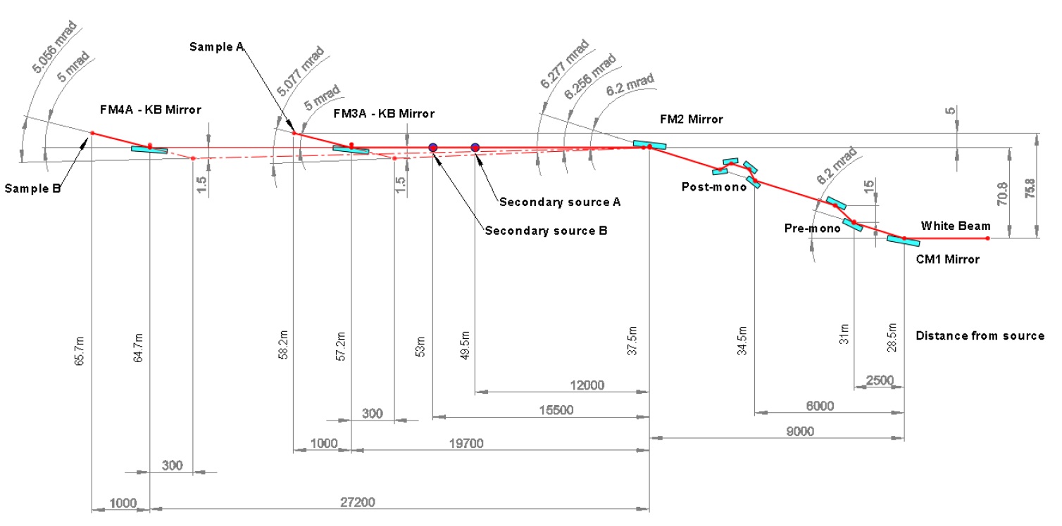
The optical layout of the beam line is shown below. A cylindrical mirror (CM1), the first optical element of the beam line, and the pre-monochromator are located in optics hutch 1 (OH), while the post-monochromator and a toroidal focusing mirror (FM2) in OH2. The secondary sources are located in the first experimental hutch (EH1), where temporary installations can be mounted. RIXS and NIXS experiments are performed in EH2 (sample A) and EH3 (sample B), respectively.
Deflection of the beam in the vertical plane is reported below.
Source
The X-ray source is a straight section of 6 m length, equipped with 4 (3) undulators with 26 (32) mm periodicity, which cover the energy range of the beam line as in the figure below.
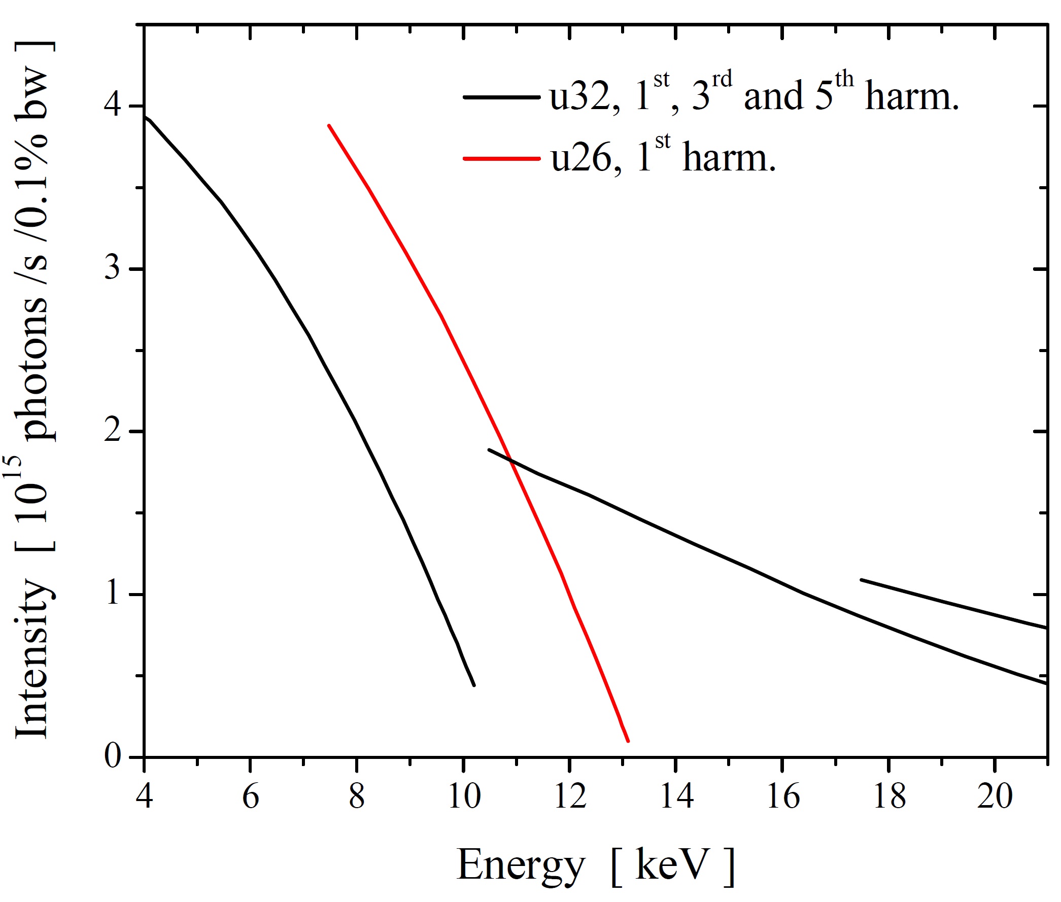
The polarization of the x-rays is parallel to the storage ring plane.
Monochromators
The beam line is equipped with a high heat-load liquid-nitrogen cooled Si(111) pre-monochromator (Kohzu), whose intrinsic energy resolution is ΔE/E = 1.1 x 10⁻⁴. The beam line can be operated in a low energy-resolution, high flux mode (few 1013 ph/s at the sample position depending on energy), or in a high energy-resolution mode, by introducing additional monochromator stages. For this purpose, a number of post-monochromators is available, namely:
- Si(311) channel-cut (ΔE/E = 2.8 x 10⁻⁵),
- Si(0nn) 4-bounce asymmetric (α = 4°) channel-cut ,
- Si(nnn) 4-bounce asymmetric (α = 5°) channel-cut.
For specific energies, back-scattering channel-cut post-monochromators are available. In particular,
- Si(844) back-scattering channel-cut (ΔE/E = 1.3 x 10⁻⁶),
- Si(664) back-scattering channel-cut (ΔE/E = 1.6 x 10⁻⁶),
- Si(nnn) back-scattering channel-cut (n=3: ΔE/E = 8.7 x 10⁻⁶, n=4: ΔE/E = 5.0 x 10⁻⁶, n=5: ΔE/E = 1.6 x 10⁻⁶).
Focusing capabilities
The divergent x-ray beam from the undulators is collimated by a cylindrical mirror (CM1) in the vertical direction and passes through the various monochromators. Focusing of X-rays is then performed in two stages: at an initial stage, the beam is focused to ~ 50 μm x 300 μm (V x H) at the position of the secondary sources (SSA and SSB) by means of a toroidal mirror (FM2). X-rays are finally re-focused at the sample position by means of a Kirkpatrick-Baez system to a spot of ~ 8 μm x 16 μm (V x H) size.
It should be mentioned, however, that the beam line allows for a certain flexibility in the choice of the spot-size at the sample position, as it can be continuously increased up to ~ 200 μm x 800 μm (V x H).
RIXS spectrometer
The RIXS spectrometer is equipped with 5 crystal analyzers, spherically bent or diced, with R = 1 or 2 m (the crystal analyzer choice is usually made depending on the working energy and need in terms of energy-resolution and flux). The energy range depends on the choice of the crystal analyser, given that the Bragg angle is constrained to 70 – 90°. The scattering geometry can be varied in both the horizontal and vertical planes.
Experiments can be performed by scanning either the incident photon energy, E1, or the scattered photon energy, E2. Note that in both cases the energy-resolution is constant throughout the scan.
See below for a complete list of analyzers available.
NIXS-XRS spectrometer
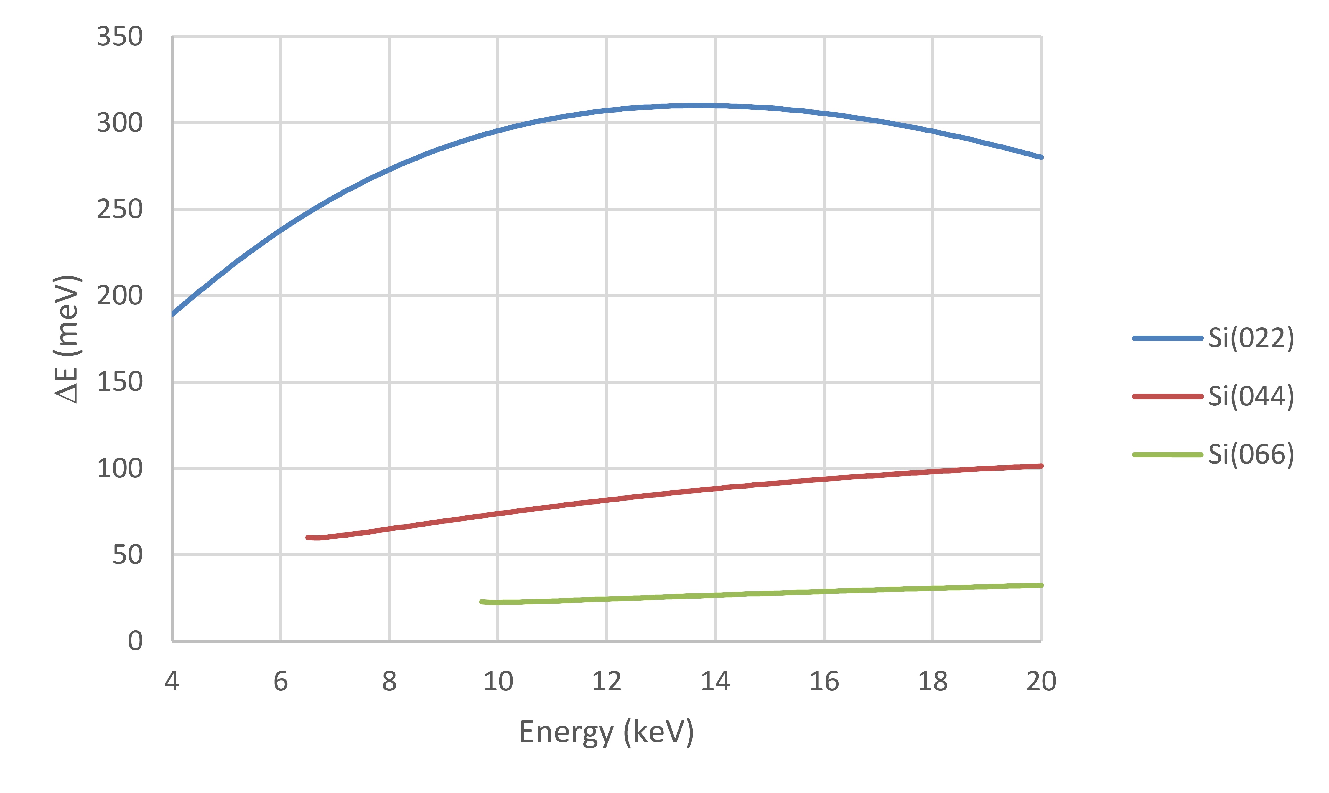
The NIXS spectrometer is equipped with 72 Si(0nn) crystal analyzers, spherically bent with R = 1 m. These are arranged in 6 vacuum chambers containing 12 analyzers each. 3 chambers span the vertical, 3 chambers the horizontal scattering plane.
The analyzers work at a fixed Bragg angle of about 88.5°, therefore at constant scattered photon energy, E2. Experiments are performed by scanning the incident photon energy, E1, such that energy-losses E1-E2 up to ~ 1000 eV match the energy window of interest.
Depending on the order n of the analyzers’ reflection, one has:
- n = 4, E2 = 6460 eV, ΔE ≈ 0.3 eV,
- n = 6, E2 = 9690 eV, ΔE ≈ 0.7 eV,
- n = 8, E2 = 12920 eV, ΔE ≈ 1.7 eV.
Note that the energy-resolution is constant throughout the scan. Typically, the n = 6 reflection is used. In this case, the largest momentum transfer |q| is about 10 Å-1, with a momentum resolution in the order of 0.2 Å-1.
With the help of this worksheet, one can easily calculate the modulus of the momentum transfer as a function of the chambers rotation angles, and incident and scattered photon energies.
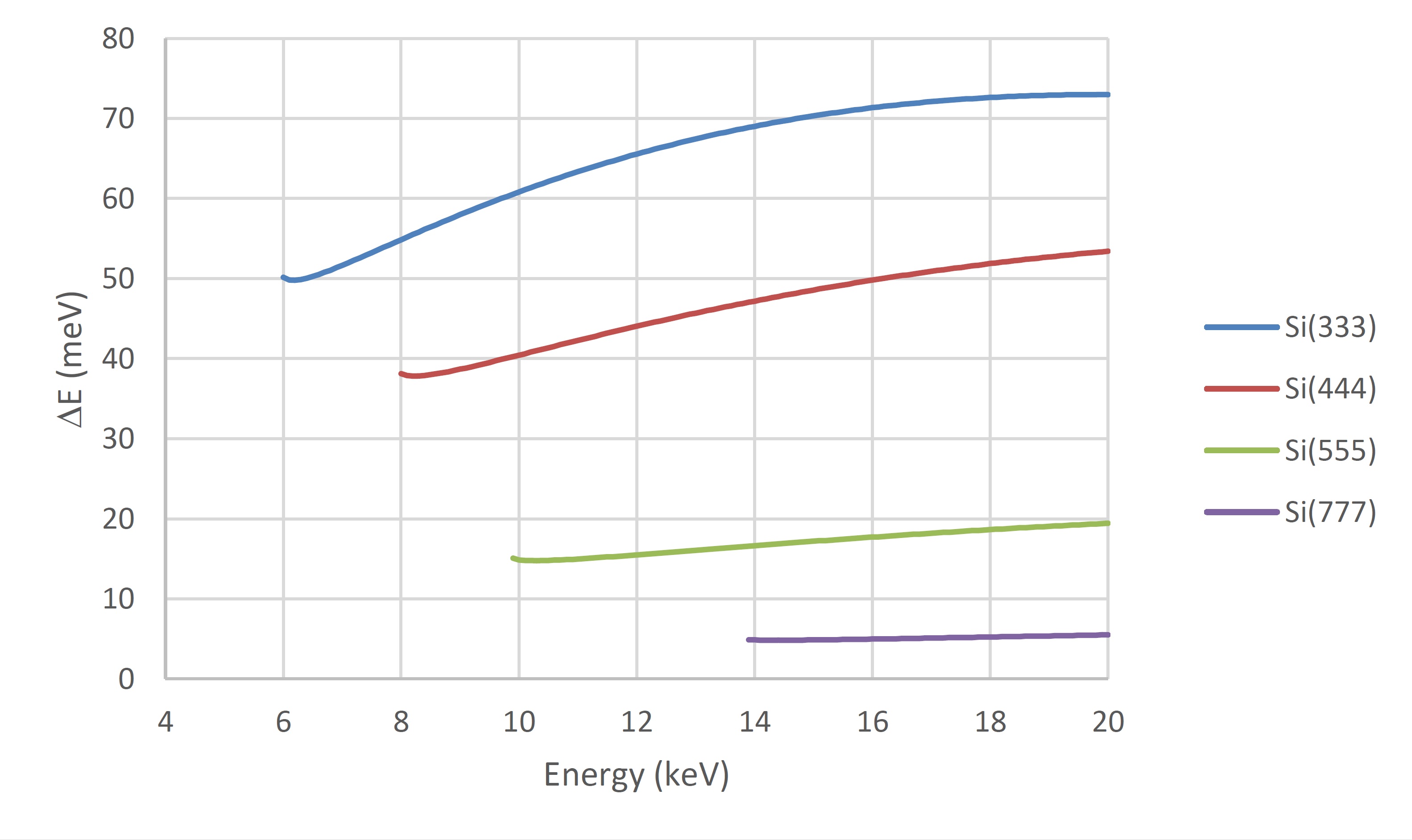
Analyzers
The analysis of the scattered photon energy in both hard x-ray IXS experiments is usually performed by means of crystal analyzers, which exploit suitable Bragg reflections. Spherically bent and diced crystal analyzers are available with several different orientations and curvature radii (R = 1 or 2 m).
A list of available materials and reflections can be found here.
Detectors
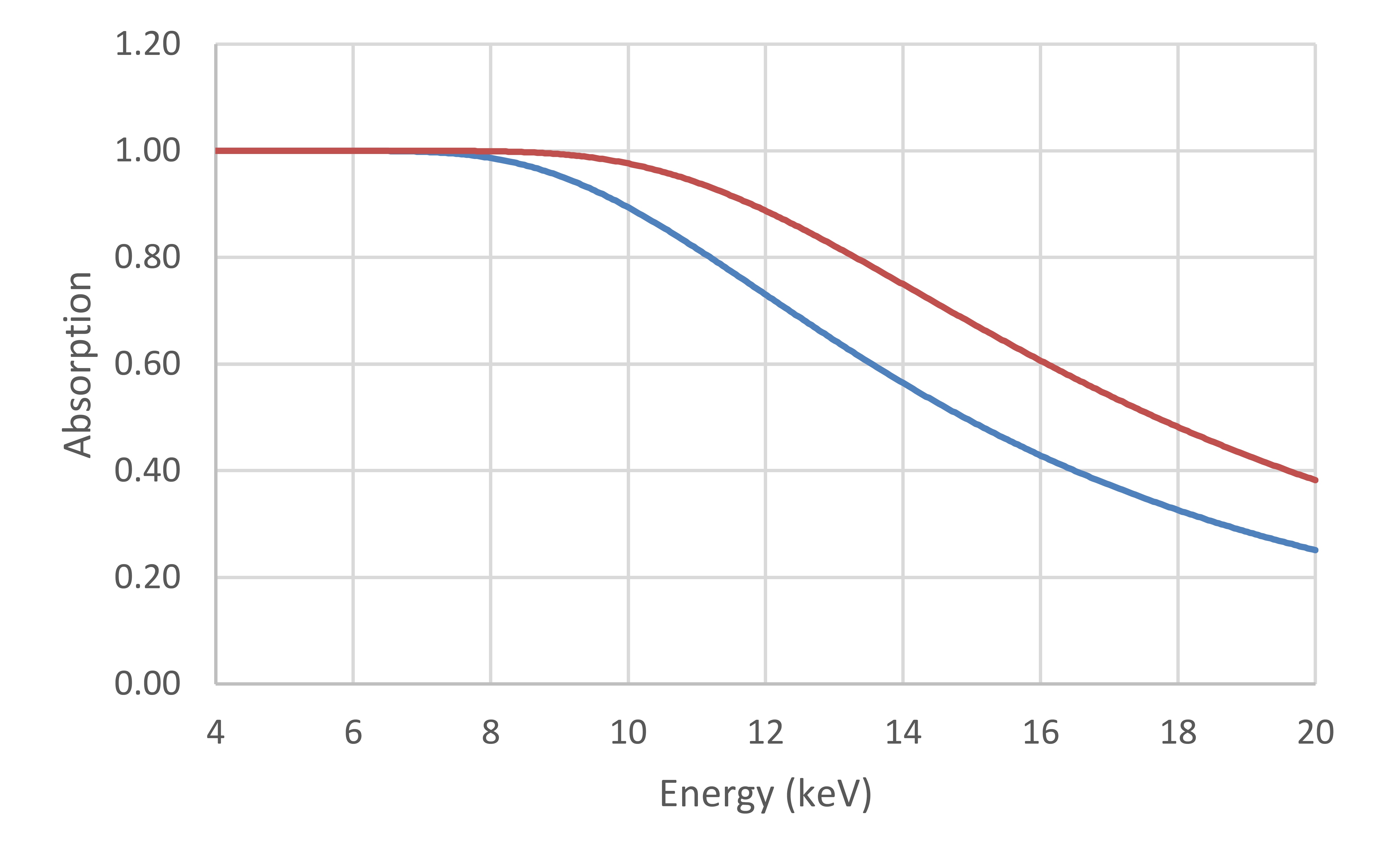
Most applications, both RIXS and NIXS, make use of the Maxipix detector developed at ESRF, i.e. a 2D photon-counting x-ray detector with 55 µm spatial resolution. The sensor thickness is 500 μm.
However, APD’s and common pin diodes (300 μm thick sensor) can also be used.
It can be useful to consider the absorption of 300 and 500 μm thick Si as a function of photon energy (below) to have an idea of the detector efficiency.
Other types of detector can be loaned from the Detector Pool.
Sample environment
Standard goniometer and goniometer head (detailed drawings are available here).
He-flow cryostat (DynaFlow), 4-300 K (detailed drawings are available here).
Heating stage, 300-450 K (detailed drawings are available here).
Liquid flow cell (detailed drawings are available here).
Other standard equipment can be reserved from the Sample Environment Pool.
partners


European Synchrotron Radiation Facility - 71, avenue des Martyrs, CS 40220, 38043 Grenoble Cedex 9, France.