- Home
- Optics hutch - OH
Optics hutch - OH
OH Photos
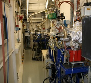
ID03 Optics Hutch: down-stream view
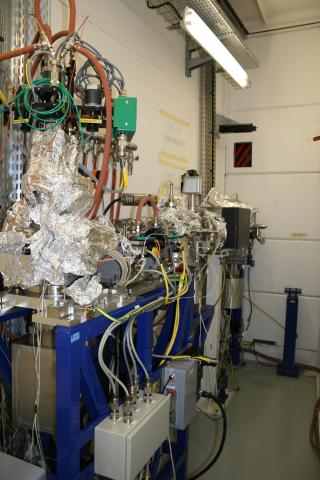
ID03 Optics Hutch: high power primary slits and attenuators at the hutch entrance
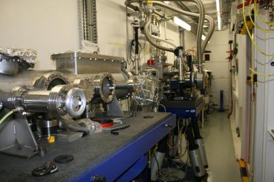
ID03 Optics Hutch: up-stream view
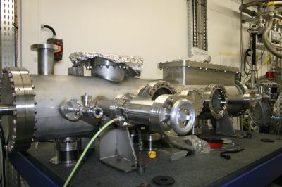
ID03 Optics Hutch: mirror vacuum vessel after the monochromator
Description
The optics hutch (OH) provides monochromatic and focused X-ray beams to both experimental hutches 1 and 2 (EH1 and EH2).
The ID03 beamline is windowless, thus the first beamline component is a differential pumping system, which decouples the vacuum of the beamline from the one of the synchrotron ring.
The first beamline optical components are the high power primary slits (see photo) installed at 31.5 m from the source. Immediately after them are placed the attenuators and a calorimeter vessel. The monochromator is positioned at 34 m from the source. It is an ESRF standard design based on the use of a monolithic channel cut Si (111) crystal cooled at liquid nitrogen temperature. Even if the monochromator energy range goes from a minimum of 3 keV up to a maximum of about 50 keV, the beamline design has been optimized for a 5-24 keV energy range.
The use of the monolithic channel-cut Si (111), more stable by design, does not allow any focalisation.
The beamline optical design is based on one cylindrical Si piece mounted on a bender to obtain a toroidal mirror with a controllable meridional focusing. The mirror, mounted at 35.5 m from the source, has a sagittal radius of 32 mm and a controllable meridional radius ranging from 5 km to 16 km. The vessel is installed on a hexapod support. A second flat mirror is mounted on the same vacuum vessel and support. Its function is to put back the X-ray beam in a horizontal direction. Both mirrors have a palladium coating. The K-absorption edge of palladium at 24.35 keV is the high energy cut-off of the beamline. With an appropriate choice of angle of incidence and of the sagittal radius (Table 1), it is possible to focus the X-ray beam to a theoretical value of about 50x30 fwhm (HxV) in any point of the two experimental hutches, EH1 and EH2.
Table 1
|
Source Distance [m]
|
Reflection angle for horizontal focussing [mrad] |
Meridional radius for vertical [km]
|
|
43.5 |
2.33 |
5.88 |
|
44.0 |
2.23 |
6.44 |
|
44.5 |
2.13 |
7.02 |
|
45.0 |
2.05 |
7.61 |
|
45.5 |
1.97 |
8.21 |
|
46.0 |
1.91 |
8.82 |
|
46.5 |
1.84 |
9.43 |
|
47.0 |
1.78 |
10.05 |
|
47.5 |
1.73 |
10.68 |
|
48.0 |
1.68 |
11.32 |
|
48.5 |
1.64 |
11.96 |
|
49.0 |
1.59 |
12.60 |
|
49.5 |
1.55 |
13.25 |
|
50.0 |
1.52 |
13.90 |
|
50.5 |
1.48 |
14.55 |
|
51.0 |
1.45 |
15.21 |
Because the reflection angle is defined by the horizontal focusing, third harmonics contamination is present when low energy x-ray beams are employed. This problem can be avoided by an accurate detuning of the 2nd monochromator crystal or by using the KB mirrors placed at the entrance of both experimental hutches.
partners


European Synchrotron Radiation Facility - 71, avenue des Martyrs, CS 40220, 38043 Grenoble Cedex 9, France.