- Home
- Users & Science
- Scientific Documentation
- ESRF Highlights
- ESRF Highlights 2003
- Method and Instrumentation
- Diffractive Optical Elements for Differential-interference Contrast X-ray Microscopy
Diffractive Optical Elements for Differential-interference Contrast X-ray Microscopy
X-ray microscopy at multi keV energies often suffers from low contrast imaging of specimens with low absorption. These specimens, called phase objects, retard or advance light that passes through them due to spatial variation in their refractive index and/or thickness. Phase contrast is often employed to image such objects, but the technique induces halo artifacts, is restricted to very thin specimen preparations, and cannot take advantage of the full condenser and objective apertures. Unlike phase contrast, differential-interference contrast (DIC) converts gradients in the object optical path length into amplitude differences that can be visualised as improved contrast in the resulting image. The phase object is sampled by two mutually coherent waves that have a lateral displacement called the shear and a phase displacement called the bias. If the shear is in the order of the object details, this is imaged into an intensity distribution that is a function of the spatial gradient of the object phase distribution. DIC does not yield accurate measurements of object's refractive index or thickness because both beams traverse the same region of the object. However, it is useful to determine the orientation of phase gradients and, capitalising on the full objective aperture, to produce thin optical sections free of obscuring disturbances from object features positioned beyond the focal plane. In the visible light-beam sharing is achieved by illuminating the phase object with a plane-polarised beam which is split by a Wollaston prism. Due to the extreme difficulties in fabricating polarising and refractive components for the X-ray region, a zone plate doublet was proposed for X-ray beam shearing [1]. Nevertheless, this zone-plate doublet does not allow control of bias retardation [2].
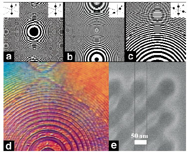
We generalised the zone plate concept to Diffractive Optical Elements (DOEs) that can incorporate both the beam shearing and bias retardation functions [3]. The DOE can be seen as an element that generates two spots with a specified phase difference between them. Moreover, its optical function is not limited to this case and can be generalised to more complex shearing configurations, as shown in Figure 173. DOEs of this type were fabricated at the Lilit beamline (Elletra) using high resolution electron-beam lithography and electroplating, by modulating the thickness of the gold absorber grown on a silicon-nitride membrane.
 |
|
Fig. 173: Optical functions and details of designed DOEs generating: two coplanar spots (a), two coaxial spots (b), four coplanar spots (c). Notice that the left and right parts in (a) are different because they have different biases (0 and |
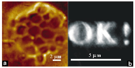
The functionality of the DOEs was tested in full-field X-ray microscopy at beamline ID21. Figure 174a displays the topography of an array of yeast cells which has an absorption lower than 2% at 4 keV. One can see that sub-micrometre details are clearly outlined. The image was obtained with the two coaxial spot DOEs which had a long depth of focus and hence the specimen could be immediately focused, avoiding cell damage. These DOEs can be introduced also in scanning microscopy and can be combined with X-ray fluorescence to obtain simultaneously topographical and morphological information from the specimen.
 |
|
Fig. 174: a) Image of an aggregate of yeast cells obtained with the two coaxial spot DOE (axial shear = 1 mm, bias = 0); b) X-ray beam shaping: continuous intensity pattern generated in a plane situated 5 cm after a DOE calculated to generate the logo 'OK !'. |
Following a similar approach, we also calculated and fabricated DOEs to perform X-ray beam shaping. They can replace the zone plate condenser to optimise the specimen illumination (e.g. uniform or a general pattern). Figure 174b displays general X-ray beam shaping obtained from such a DOE.
In conclusion we have demonstrated phase DOEs that, for the available X-ray sources, accomplish a variety of new functions useful for X-ray microscopy. Moreover, the freedom in redistributing the wavefront suggests a maskless way to transfer the information onto a substrate. The sensitive material on the surface can be either a resist or a precursor gas, in the case of chemical vapour deposition, whose interaction with the surface can be induced by photons.
References
[1] T. Wilhein, B. Kaulich, E. Di Fabrizio, F. Romanato, S. Cabrini, and J. Susini, Appl. Phys. Lett. 78, 2082 (2001).
[2] B. Kaulich, T. Wilhein, E. Di Fabrizio, F. Romanato, M. Altissimo, S. Cabrini, B. Fayard, and J. Susini, J. Opt. Soc. Am A 19, 797-806 (2002).
[3] E. Di Fabrizio, D. Cojoc, S. Cabrini, B. Kaulich, T. Wilhein, and J. Susini, J. Phys. IV France 104, 177-183 (2003)
Principal Publication and Authors
E. Di Fabrizio (a), D. Cojoc (a,f), S. Cabrini (a), B. Kaulich (b), J. Susini (c), P. Facci (d), T. Wilhein (e), Optics Express, 11, 2278 (2003).
(a) Lilit Beamline, TASC-INFM, Elettra Sincrotrone, Trieste (Italy)
(b) Elettra Sincrotrone, Trieste (Italy)
(c) ESRF
(d) INFM - University of Modena (Italy)
(e) University for Applied Sciences, Remagen (Germany)
(f) 'Politehnica' University of Bucharest (Romania)
partners


European Synchrotron Radiation Facility - 71, avenue des Martyrs, CS 40220, 38043 Grenoble Cedex 9, France.