- Home
- Users & Science
- Scientific Documentation
- ESRF Highlights
- ESRF Highlights 2012
- Accelerator and X-ray Source
- Permanent magnet steerers for canted beamlines
Permanent magnet steerers for canted beamlines
Phase I of the ESRF upgrade includes a number of canted beamlines (ID16, ID30 and ID23). In a canted scheme, the radiation axes from two sets of insertion devices are angularly separated by means of small static steerers that deflect the electron beam accordingly. A typical steerer layout consists of three magnets: one installed in the middle of the straight section and the two others, each with half the opposite magnetic strength of the middle one, installed at either end of the straight section. This configuration is generally achieved with conventional electromagnet structures. An interesting alternative based on permanent magnets has been designed by the ID group. The new design aims to minimise the space occupancy and to control the magnetic fringe field along the beam path in order to eliminate any impact on the spectrum quality of the neighbouring undulators [1].
 |
|
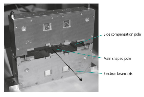
Fig. 152: Permanent magnet steerer before installation on the ID16 straight section. |
Figure 152 shows a permanent magnet steerer (PMS) before installation in ID16, at the end of a straight section. The shape of the central main pole is optimised for a flat-top transverse field and ensures negligible impact on the beam dynamics. The residual field outside the structure is controlled through the implementation of side openings (side compensation poles). The magnetic measurements carried out on different PMS are in excellent agreement with expectations. In particular, the distance between the last and first magnets of two undulators separated by the middle PMS could be reduced to 350 mm without impacting the phase error of either undulator. The first set of PMS was installed on ID16 in summer 2012 and provides a canting angle of 5.4 mrad between the two future branches of ID16 (NINA). No specific impact on the electron beam dynamics has been observed so far. Further interesting results are anticipated and will be communicated once ID16 comes into operation.
References
[1] Permanent Magnet Steerers for Canted Undulators at the ESRF, G. Le Bec and J. Chavanne, NIM A: Accelerators, Spectrometers, Detectors and Associated Equipment, Volume 664, Issue 1, February 2012, p. 214-222.
partners


European Synchrotron Radiation Facility - 71, avenue des Martyrs, CS 40220, 38043 Grenoble Cedex 9, France.