- Home
- Users & Science
- Scientific Documentation
- ESRF Highlights
- ESRF Highlights 2009
- Accelerator and X-ray Source
Accelerator and X-ray Source
Throughout 2009, the Accelerator and Source Division has continued its efforts to ensure reliable operation as well as preparing for the forthcoming upgrade. A number of developments have been carried out; the most important of these are described hereafter.
Beam parameters of the storage ring
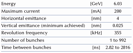
Table 2 presents a summary of the characteristics of the storage ring electron beam.
 |
|
Table 2: Principal characteristics of the electron beam. |
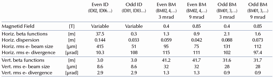
Table 3 gives the main optic functions, electron beam size and divergence at various source points. For insertion device source points, the beta functions, dispersion, sizes and divergences are calculated in the middle of the straight section.
Two representative source points for each type of bending magnet (even or odd number) have been selected, corresponding to observation angles of 3 and 9 mrad from the exit. The bending magnets are such that the magnetic field is 0.4 T and 0.85 T at the tangent point when the radiation is extracted at 3 and 9 mrad angles, respectively. Electron beam profiles are Gaussian and the size and divergence are presented in terms of rms quantities. The associated full width half maximum sizes and divergences are 2.35 times higher. Horizontal electron beam sizes and divergences are given for the uniform filling modes and apply to almost all filling patterns except for single bunch, for which a slightly larger size and divergence are attained because of the increased energy spread of the electron beam. Vertical electron beam sizes and divergences apply to uniform, 2 x 1/3, and hybrid filling modes only. To increase the lifetime of the stored beam, the vertical beam sizes and divergences are increased by about 50% in the 16 and 4 bunch filling patterns.
 |
|
Table 3: Beta functions, dispersion, rms beam size and divergence for the various source points. |
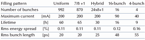
The lifetime, bunch length and energy spread mainly depend on the filling pattern. These are given in Table 4 for a few representative patterns. Note that in both 16-bunch and 4-bunch filling patterns, the energy spread and bunch length decay with the current (the value indicated in the table corresponds to the maximum current). The bunch lengths are given for the usual radio frequency accelerating voltage of 9 MV (8 MV for 16-bunch and 4-bunch).
 |
|
Table 4 : Current, lifetime, bunch length and energy spread for a selection of filling modes. |
Accelerator operation
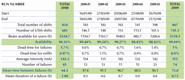
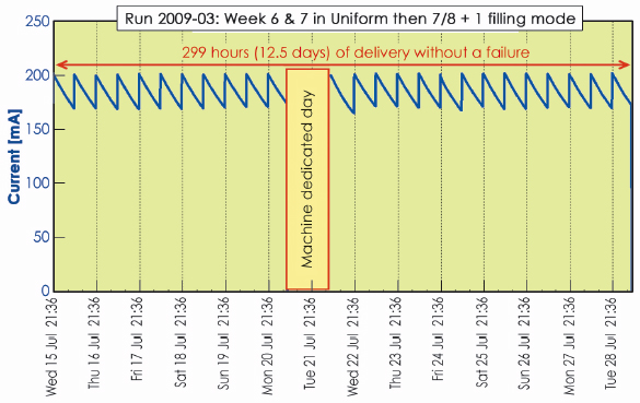
In 2009, 701.5 shifts (5612 hours) of beam were initially scheduled. Of these 5612 hours, 5510 were effectively delivered (including 48 hours of refill). This represents a beam availability of 99.04%, which is a record figure in the history of the ESRF. Table 5 presents an overview of operation in 2009.Dead time due to failures accounts for the remaining 0.96%. The number of failures is lower compared to the previous years, thus leading to an all time record Mean Time Between Failures of 75.8 hours. This excellent performance was the consequence of multiple effects including an active preventive maintenance policy as well as the protection against electrical mains drops provided by the new HQPS II system which has been operational since July 2008. Twenty long delivery periods (i.e. more than 100 hours) without a single interruption took place in 2009. In particular, the last 2 weeks of the third run when the beam was delivered continuously for 12.5 days, only interrupted by the scheduled Machine Dedicated Day (Figure 158).
 |
|
Table 5: Overview of storage ring operation in 2009. |
 |
|
Fig. 158: An example of two weeks of delivery without a single failure, interrupted only by a scheduled Machine Dedicated Day. |
All the 2009 shutdowns were quite busy due to preparation of the upgrade including straight section lengthening, installation of a new Linac gun, new diagnostics tools, etc. The highlight of this year was the completion of the installation of the Libera BPMs (details below) with no disturbance to operation.
Filling patterns
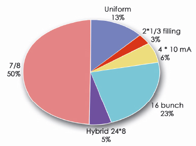
Figure 159 presents the distribution of filling modes delivered in 2009. Compared to 2008, no significant changes were made to the distribution. The filling mode labelled “7/8 + 1” developed in 2006-2007 has become the standard multibunch mode. It provides an interesting compromise combining the benefit of a long lifetime multibunch mode while allowing time structure studies with the single bunch.
 |
|
Fig. 159: Distribution of longitudinal filling modes in 2009. |
partners


European Synchrotron Radiation Facility - 71, avenue des Martyrs, CS 40220, 38043 Grenoble Cedex 9, France.