- Home
- Users & Science
- Scientific Documentation
- ESRF Highlights
- ESRF Highlights 2007
- Surface and Interface Science
- Revealing the core structure of defects
Revealing the core structure of defects
Nanostructures must be kept free of defects during device fabrication in order to obtain the desired electronic properties. The structure, nature, and location of defects can be determined by transmission electron microscopy (TEM), but it remains a destructive method. Diffuse X-ray scattering on the other hand is a well-established non destructive method for the investigation of defects in crystals [1]. Usually, the scattering from the deformed lattice around the defects is measured close to allowed Bragg peaks (the Huang scattering) and is used for the defect investigation. However, here the contribution of the defect cores is weak due to the rather small volumes of the defect cores and to the strong contribution of the Huang scattering, so that the investigation of the structure of the defect core is difficult. As a consequence, not only traditional X-ray diffuse scattering but also high-resolution TEM (HRTEM) measurements often fail to observe the atomic displacement field of the atoms in the core of defects.
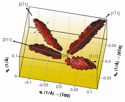
We have developed a novel X-ray method to study the defect cores directly. A forbidden reflection is used for the suppression of the displacement-field scattering so that the scattered intensity consists mainly of the scattering from the core. Employing this method, we investigated the structure of the cores of extrinsic stacking faults created in Si crystal after amorphising ion implantation and subsequent annealing. The diffuse X-ray scattering has been measured on beamline ID01. A three-dimensional intensity distribution was collected by a linear detector perpendicular to the sample surface around the (200) forbidden reflection. The diffuse scattering was concentrated in intensity streaks along <111> directions visible in Figure 84.
 |
|
Fig. 84: Three dimensional reciprocal-space distribution around h (200). The scattered intensity is concentrated in streaks along <111> perpendicular to the stacking fault planes. The white dashed line denotes the trajectory along which the line scan in Figure 85 was extracted. |
The diffuse part of the scattered intensity from small defects in non-correlated random positions is a coherent superposition of two contributions I(Q)~|E1(Q)+E2(Q)|2, where E1 describes the scattering from the displacement field around a single defect and E2 = f(Q)![]() c
c ![]() (Rc)exp(-iQ.Rc) is the scattering from the defect core,
(Rc)exp(-iQ.Rc) is the scattering from the defect core, ![]() (Rc) is the shape function of a single defect core, f(Q) is the atomic scattering factor and Rc is the position of the atoms of the defect cores. If F0(h) = 0 as for the Si (200), the displacement-scattering term (E1) is weak or can be neglected. Thus, the diffuse scattering results mainly from the defect cores.
(Rc) is the shape function of a single defect core, f(Q) is the atomic scattering factor and Rc is the position of the atoms of the defect cores. If F0(h) = 0 as for the Si (200), the displacement-scattering term (E1) is weak or can be neglected. Thus, the diffuse scattering results mainly from the defect cores.
The Si crystal contains randomly-distributed extrinsic stacking faults which lie in {111} planes having the Burgers vector b=1/3<111> perpendicular to the planes. The core of such faults consists of two extra {111} planes, having the nominal distance ![]() 0=a
0=a![]() 3/4. From symmetry considerations it follows that the reciprocal-space distribution of the scattered intensity I(Q) is concentrated along <111> lines, perpendicular to the loop planes. Thus, the intensity observed in Figure 84 stems from the diffuse scattering of the cores of stacking faults in Si. From the fit of the streak cross-section (see black dashed line in Figure 84), the mean radius R0 = (30±2) nm of the faults follows.
3/4. From symmetry considerations it follows that the reciprocal-space distribution of the scattered intensity I(Q) is concentrated along <111> lines, perpendicular to the loop planes. Thus, the intensity observed in Figure 84 stems from the diffuse scattering of the cores of stacking faults in Si. From the fit of the streak cross-section (see black dashed line in Figure 84), the mean radius R0 = (30±2) nm of the faults follows.
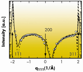
The intensity distribution along the streaks I(q111) is plotted in Figure 85. Here q111 is the coordinate of q along the [111] direction depicted in Figure 84 (see white dashed lines); q111= 0 corresponds to the reciprocal lattice point h (200), forbidden for Si. We have fitted this distribution to the theory described above; the fit depends on only one free parameter ![]() , which is the distance between the two extra planes forming the core of the extrinsic stacking-fault. After taking into account the scattering around several allowed reciprocal-space points, the fit reveals a core displacement of
, which is the distance between the two extra planes forming the core of the extrinsic stacking-fault. After taking into account the scattering around several allowed reciprocal-space points, the fit reveals a core displacement of ![]() =(2.1±0.2) Å. The correspondence of the measured and fitted intensity distribution is good (see Figure 85, full line), revealing the compression of the {111} planes in the defect cores (
=(2.1±0.2) Å. The correspondence of the measured and fitted intensity distribution is good (see Figure 85, full line), revealing the compression of the {111} planes in the defect cores (![]() <
< ![]() 0). These results are well supported by atomistic simulations (see Figure 85, dashed line).
0). These results are well supported by atomistic simulations (see Figure 85, dashed line).
 |
|
Fig. 85: Distribution of the measured intensity (points) along the trajectory denoted in Figure 84, along with its theoretical fit using the continuum approach (full line) and atomistic simulations (dashed). |
To conclude, diffuse X-ray scattering around a forbidden reciprocal lattice point is well suited for the study of the cores of extrinsic stacking faults in Si. This novel, highly sensitive and destruction-free technique allows detection of stacking faults and characterisation of the small compression in their core. This unique method can also be extended to other kind of defects.
References
[1] M.A. Krivoglaz, X-ray and Neutron Diffraction in Non-ideal Crystals (Springer 1996).
Principal publication and authors
M.-I. Richard (a, b), T.H. Metzger (a), V. Holy (c), K. Nordlund (d), Phys. Rev. Lett. 99, 225504 (2007).
(a) ESRF
(b) Département de Recherche Fondamentale sur la Matière Condensée/SP2M/NRS, CEA Grenoble (France)
(c) Faculty of Mathematics and Physics, Charles University, Prague (Czech Republic)
(d) Accelerator Laboratory, University of Helsinki (Finland)
partners


European Synchrotron Radiation Facility - 71, avenue des Martyrs, CS 40220, 38043 Grenoble Cedex 9, France.