- Home
- Users & Science
- Scientific Documentation
- ESRF Highlights
- ESRF Highlights 2003
- X-ray Absorption and Magnetic Scattering
- Experimental Exploitation of Sum Rules in X-ray Resonant Raman Scattering
Experimental Exploitation of Sum Rules in X-ray Resonant Raman Scattering
In X-ray resonant Raman scattering (RRS) the sample is excited with monochromatic incident X-rays (h![]() in) and outgoing photons are measured vs. energy (h
in) and outgoing photons are measured vs. energy (h![]() out). At an absorption edge, the process is resonant and gives site and element-specific information. In spite of the success of RRS, the crucial area of sum rules remained so-far unexplored although theoretical work on magnetic systems was already done in the mid 90's [1,2]. The lack of experimental work came from requirements for a completely new experimental approach.
out). At an absorption edge, the process is resonant and gives site and element-specific information. In spite of the success of RRS, the crucial area of sum rules remained so-far unexplored although theoretical work on magnetic systems was already done in the mid 90's [1,2]. The lack of experimental work came from requirements for a completely new experimental approach.
Let us describe the ground-state in terms of charge and angular-momentum expectation values in a multipolar expansion and consider the electric-dipole transitions. X-ray absorption is a first-order process giving access to ground-state properties of first order in magnetic-circular dichroism and of second order in linear dichroism. On the other hand, RRS is a second-order process where sum rules give information up to the fourth order.
The sum rules require the intensity of a given edge with well-defined quantum number j. Since RRS depends on h![]() in and h
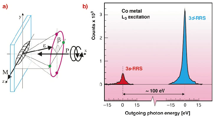
in and h![]() out, the integrated RRS (IRRS) signal is obtained by integrating along both energy axis. In the theory the IRRS signal is a sum of terms containing ground-state moments of given order times an angular distribution with a symmetry characteristic of that order. As a consequence, once a convenient geometry is chosen, the angular dependence of the IRRS signal gives direct information on the moments of given order. This concept is understood by a qualitative argument on the charge quadrupole in the IRRS experiment in perpendicular geometry (Figure 114a). Let us consider the IRRS-sum signal for opposite circular polarisations without measuring the scattered X-ray polarisation. The situation has left-right mirror symmetry and the IRRS-sum signal in the green points does not distinguish between opposite magnetisation directions. Along the cone (magenta trajectory) the IRRS-sum signal changes due to the charge quadrupole of the sample and the difference between the points in vertical (magenta) and horizontal (green) plane is characteristic for the charge quadrupole. This "conical scan" has the advantage that the emission always has constant angle with the surface so that the self-absorption does not change along the trajectory.
out, the integrated RRS (IRRS) signal is obtained by integrating along both energy axis. In the theory the IRRS signal is a sum of terms containing ground-state moments of given order times an angular distribution with a symmetry characteristic of that order. As a consequence, once a convenient geometry is chosen, the angular dependence of the IRRS signal gives direct information on the moments of given order. This concept is understood by a qualitative argument on the charge quadrupole in the IRRS experiment in perpendicular geometry (Figure 114a). Let us consider the IRRS-sum signal for opposite circular polarisations without measuring the scattered X-ray polarisation. The situation has left-right mirror symmetry and the IRRS-sum signal in the green points does not distinguish between opposite magnetisation directions. Along the cone (magenta trajectory) the IRRS-sum signal changes due to the charge quadrupole of the sample and the difference between the points in vertical (magenta) and horizontal (green) plane is characteristic for the charge quadrupole. This "conical scan" has the advantage that the emission always has constant angle with the surface so that the self-absorption does not change along the trajectory.
 |
|
Fig. 114: a) schematics of the experiment. b) traditional RRS spectrum of Co metal. |
In 3d magnetic systems, the scattering channel with the best contrast contains a final state with a 3s hole, i.e. 2p63dn ![]() 2p53dn+1
2p53dn+1 ![]() 2p63s12pn+1. The experimental problem is how to measure the IRRS signal along trajectories such as the conical scan or other trajectories required since this is basically impossible with traditional RRS instruments based on gratings or crystals. The new idea is to measure directly the intensity integrated along h
2p63s12pn+1. The experimental problem is how to measure the IRRS signal along trajectories such as the conical scan or other trajectories required since this is basically impossible with traditional RRS instruments based on gratings or crystals. The new idea is to measure directly the intensity integrated along h![]() out with a suitable device and to measure it vs. h
out with a suitable device and to measure it vs. h![]() in and angles. The concept is understood from Figure 114b showing the traditional RRS spectrum of Co metal (L3 excitation) containing the 3s region (red) and 3d valence region (blue). The interesting signal is the integral of the 3s channel, which is either measured using: (i) a filter of atomic number Z-1 (Fe in our example) in front of a diode; (ii) a bandpass defined with a multilayer, as we did recently, which improves selectivity and versatility. The signal is measured vs. h
in and angles. The concept is understood from Figure 114b showing the traditional RRS spectrum of Co metal (L3 excitation) containing the 3s region (red) and 3d valence region (blue). The interesting signal is the integral of the 3s channel, which is either measured using: (i) a filter of atomic number Z-1 (Fe in our example) in front of a diode; (ii) a bandpass defined with a multilayer, as we did recently, which improves selectivity and versatility. The signal is measured vs. h![]() in (IRRS spectra) and integrated along h
in (IRRS spectra) and integrated along h![]() in after background subtraction.
in after background subtraction.
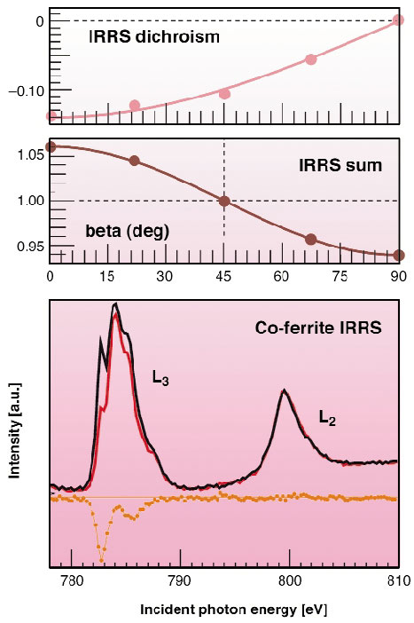
Figure 115 gives the IRRS spectra of Co in a ferrite measured in the green points of Figure 114 with opposite helicities together with the dichroism (orange). The angular dependence of the integrated dichroism (pink curve) and of the IRRS-sum signal (brown curve) can be used together with other scans based on small sample rotations around the y-axis (Figure 114). In this way, and by taking advantage of absorption measurements, one obtains information on moments up to order four as in the original reference.
 |
|
Fig. 115: Lower panel: Integrated RRS (IRRS) spectra of Co in a ferrite in the geometry of Figure 114 (dichroism in orange). Mid panel: IRRS sum signal along the conical scan (brown). Top panel: IRRS dichroism (pink). |
References
[1] G. van der Laan, B.T. Thole, J. Phys. Condens. Matter 7, 9947 (1995).
[2] M. van Veenendaal, P. Carra, B.T. Thole, Phys. Rev. B 54, 16010 (1996).
Principal Publication and Authors
L. Braicovich (a), A. Tagliaferri (a), G. van der Laan (b), G. Ghiringhelli (a), N.B. Brookes (c), Phys. Rev. Lett. 90, 117401 (2003).
(a) INFM, Dipartimento di Fisica del Politecnico, Milano (Italy)
(b) Daresbury Laboratory, Warrington (UK)
(c) ESRF
partners


European Synchrotron Radiation Facility - 71, avenue des Martyrs, CS 40220, 38043 Grenoble Cedex 9, France.