MSGC electronics
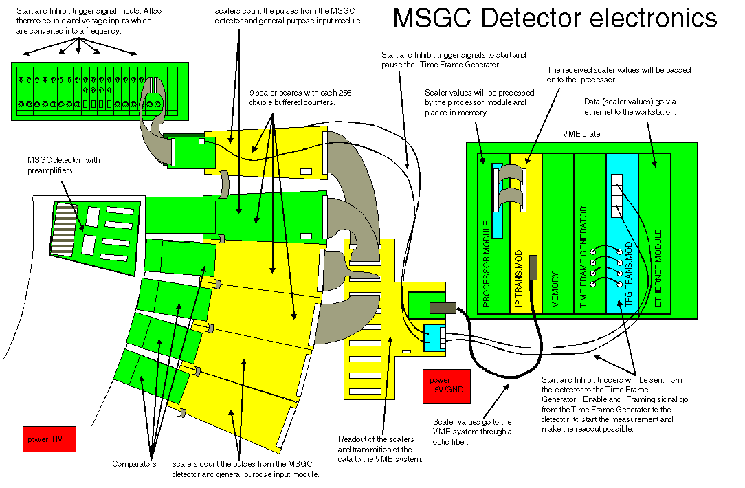
In the detector, a negative potential is applied to the drift electrode. The anode strips are grounded via the DC connection to the preamplifier. Each anode strip is individually equipped with a charge sensitive preamplifier-shaper, discriminator and scaler. The rear edge of the strips is wire bonded to the electronics. The next figure shows the schematics of the detector electronics.
 |
|
MSGC detector electronics overview (click on the image to zoom in). The inset shows one of the four assembled carrier boards and its fragment. |
Legend:
Start and inhibit trigger signal inputs. Also thermo couple and voltage inputs which are converted into a frequency.
Scalers count the pulses from the MSGC detector and general purpose input output module.
9 scaler boards with each 256 double buffered counters.
Start and inhibit trigger signals to start and pause the Time Frame Generator.
Scaler values will be processed by the processor module and placed in memory.
The received scaler values will be passed on to the processor.
Data (scaler values) go via ethernet to the workstation.
MSGC detector with preamplifiers
Comparators
Scalers count the pulses from the MSGC detector and general purpose input module.
Readout of the scalers and transmission of the data to the VME system.
Scaler values go to the VME system through an optic fiber.
Start and inhibit triggers will be sent from the detector to the Time Frame Generator.
Enable and Framing signal go from the Time Frame Generator to the detector to start the measurement and make the readout possible.
Literature:
I. P. Dolbnya, H. Alberda, F. G. Hartjes, F. Udo, R. E. Bakker, M. Konijnenburg, E. Homan, I. Cerjak, P. Goedtkindt and W. Bras, A fast position sensitive MSGC detector at high count rate operation, Rev. of Sci. Instrum. 73 (2002), no. 11, 3754-3758.


